SourceMeter® Instrument User's Manual Section 7: Measuring I-
V characteristics of FETs
2450-900-01 Rev. E / August 2019 7-3
Connections for the SCPI command set
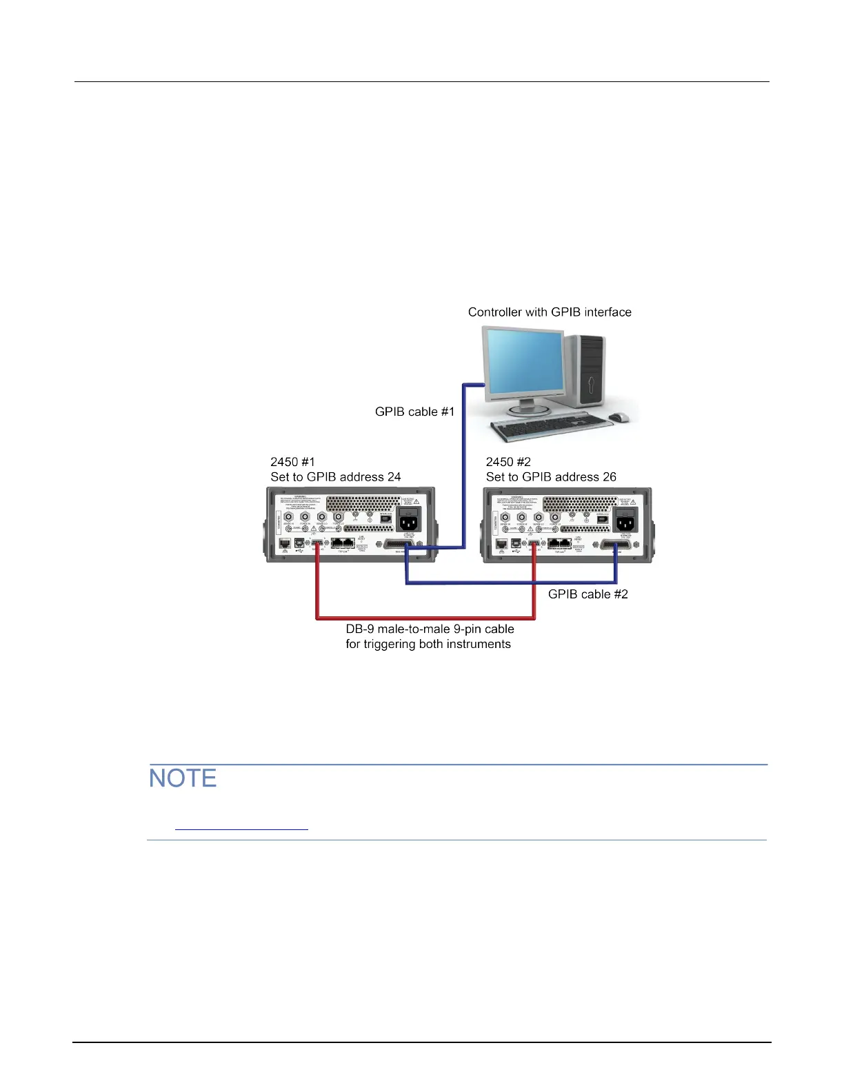
If you are using the SCPI command set, connect a DB-9 male-to-male cable between the digital I/O
connectors on the back of each of the instruments, as shown in the figure below.
For more detailed information about the digital I/O connector pins, see “Digital I/O” in the Model 2450
Reference Manual.
Figure 36: GPIB and DB-9 cable connections for the SCPI programming example
The figure above also shows the communication cable connections if you are using the GPIB remote
communication interface. GPIB cable #1 connects the GPIB port on the computer (controller) to the
IEEE-488 connector on the rear panel of 2450 #1. GPIB cable #2 connects the IEEE-488 connectors
of the two 2450s.
Each 2450 must have a different GPIB address. You can set this up using the front panel. For details,
see Set the GPIB address (on page 3-3
).
If you are using USB cables to connect the computer and 2450 instruments, each instrument must be
connected to the computer with a separate USB cable.
If you are using ethernet connections to connect the computer and 2450 instruments, the instruments
and computer must be connected using an ethernet switch or hub.