Giving Demos of M SO400 0 Features
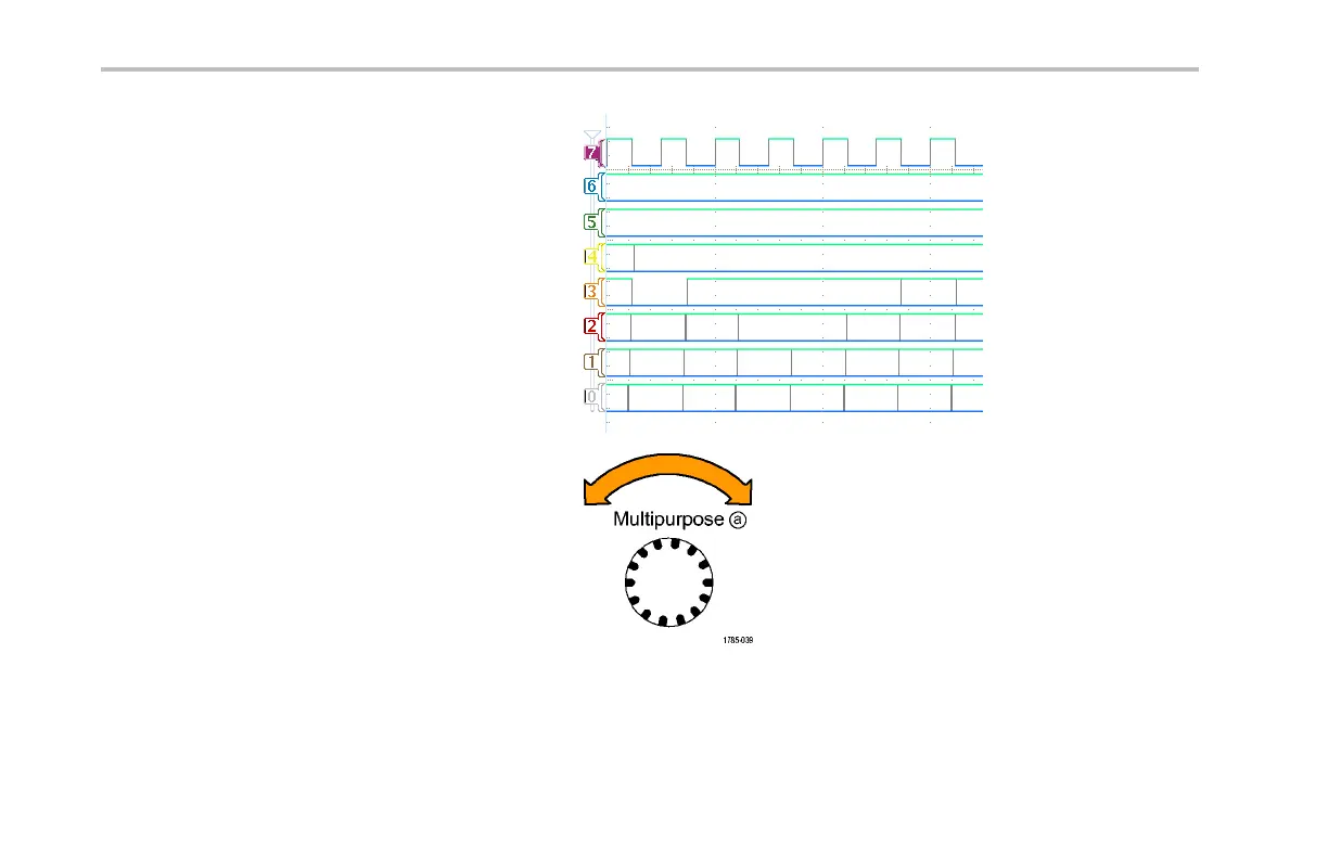
You should now see all seven counter data
signals and the counter clock. Notice the
upside down triangle on the left side of the
display, above the channel 7 marker. This is
the channel’s group marker.
When multiple channels are placed adjacent to
each other on the screen, they form a group.
Groups provide y ou with an easy way to set
up multiple digital channels at once. You can
use the group to ea sily position multiple digital
waveforms on the scre en. You can also use
them to easily alter the voltage thresholds for
all the channels in the g roup.
16. Positioning a group of signals on the screen
is easy. To demonstrate this, push the blue
front-panel D15–D0 butto n, turn multipurpose
knob a and notice that the oscilloscope
highlights each le ft-side channel marker in
turn.
74 Tektronix 4000 Oscilloscope Demo Instruction Manual
 Loading...


