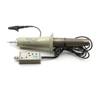
P6137 10X Passive Probe Instructions
5
Probe Adjustment/Maintenance
WARNING. The following servicing instructions are for use by qualified
personnel only. To avoid electrical shock, do not perform any probe maintenance
while the probe is connected to a signal source.
Probe Compensation
Due to variations in oscilloscope input characteristics, probe low-frequency
compensation should be checked and adjusted after moving the probe from one
input to another.
To adjust low-frequency compensation, apply a 1 kHz square-wave signal (such
as an oscilloscope calibrator output) to the probe tip. Using a low-reactance
alignment tool, adjust the probe’s compensation capacitor through the hole in the
compensation box to obtain the squarest waveform at the front corner.
High-frequency compensation seldom requires adjustment; however, if the probe
has excessive high-frequency aberrations or insufficient bandwidth, then adjust
the high-frequency compensation.
Typical test equipment required includes a Tektronix PG506A pulse generator
(rise time of ≤1 ns) & Tunnel Diode Pulser (Tektronix part number 067-0681-01)
with pulse rise time of ≤125 ps. Use a 50 W terminated BNC-to-compact probe
tip adapter (such as Tektronix part number 013-0227-00) to connect the probe to
the equipment.
To adjust high-frequency compensation, first remove the plastic cover (see the
parts replacement procedures). Next, adjust R1 and R3 (shown in Figure 6) for
best long-term flatness. Finally, adjust R2 and C1 for best short-term flatness.
Due to interaction between controls, the adjustment procedure may need to be
repeated. Refer to Figure 7 for additional information about compensation
procedures.
 Loading...