Performance Verification
Count
Setup > Settings > Traces > Function
1000 (Count box checked)
LF Path
Setup > Acquire > Input Params
Use Low Freq Signal path box
unchecked
4. Set the markers for Noise Mode (dBm/Hz) operation:
a. Select Mark
ers located at the bottom right of the screen on the status bar
to display the Markers control bar.
b. Click the down arrow on the left side of the Markers control bar to view
the Select a Marker dropdown menu. Select Add Marker to add the
MR marker
.
c. Select Add Marker againtoaddtheM1marker.
d. Select D
efine located on the right side of the Markers control bar to open
the Define Markers control panel.
e. Select Power from the Readouts dropdown menu. This sets units to
dBm/Hz.
5. Set the RSA5100B to each of the Center Frequencies listed in the following
tablebypressingtheFreq key and entering the value listed. After averaging
is completed, press the Peak key on the Markers control bar for each Center
Frequency setting. As noted below, if the peak is on a spur, not the noise floor,
plac
e the marker on the highest point of the noise floor.
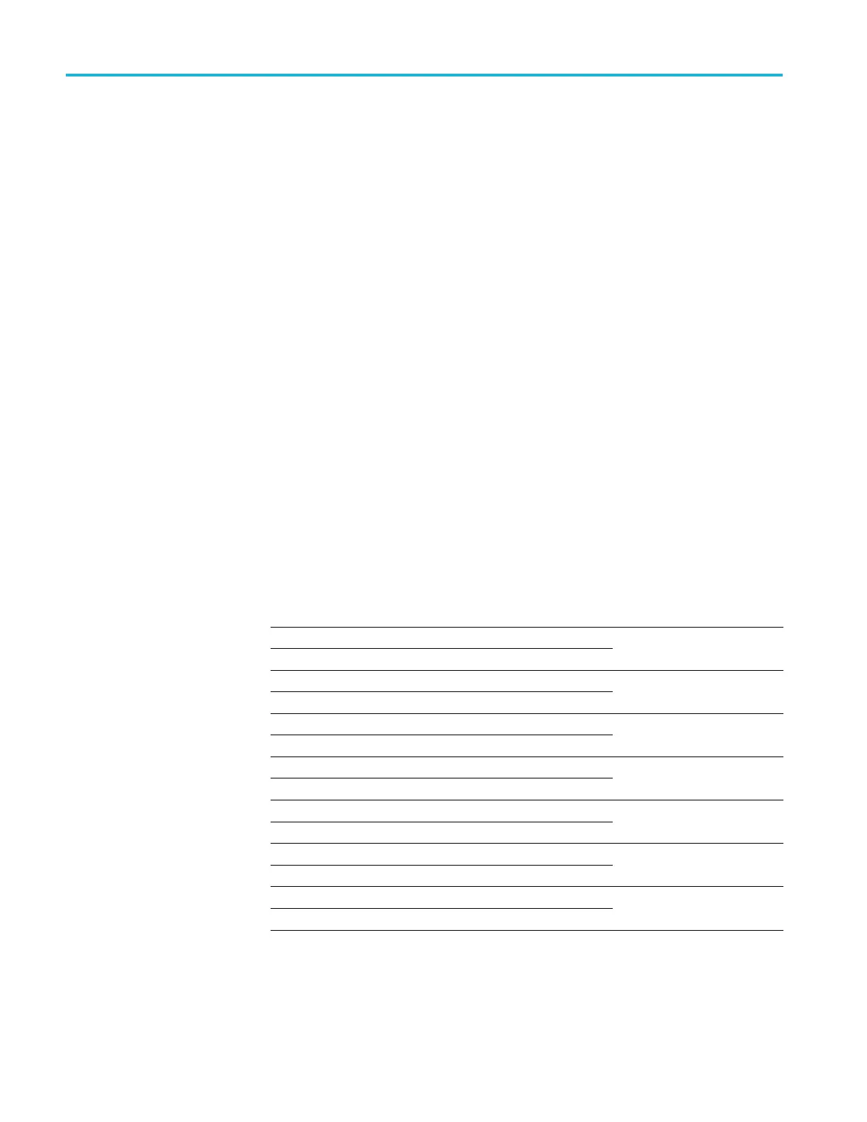
Table 76: Frequencies of interest for DANL (RF path)
Center frequency Marker noise level Frequency range
1.1 MHz
9.9 MHz
1MHz-10MHz
(All models)
10 MHz
1.99 GHz
10 MHz - 2.0 GHz
(All models)
2.01 GHz
2.99 GHz
2.0 GHz - 3.0 GHz
(All models)
3.01 GHz
3.99 GHz
3.0 GHz - 4.0 GHz
(RSA5106B/5115B/5126B)
4.01 GHz
6.2 GHz
4GHz-6.2GHz
(RSA5106B/5115B/5126B)
6.2 GHz
15 GHz
6.2GHz-15GHz
(RSA5115B/5126B)
15 GHz
26.5 GHz
15 GHz -26.5 GHz
(RSA5126B)
6. Enter the highest noise level for each of the frequency ranges shown into the
test record. (Limits are shown in the test record.)
116 RSA5100B Series Technical Reference
 Loading...


