Removal and Replacement
6–20
TDS 340A, TDS 360 & TDS 380 Technical Reference
Main Board Assembly
Required tools: a screwdriver with a size T-15 TorxR tip (Items 1 and 2),
BNC wrench (Item 15), BNC fixture (Item 16), and soldering iron (Item 13).
1. Remove the front trim ring as described on page 6–14.
2. Set the oscilloscope so its top side is down on the work surface and its rear is
facing you.
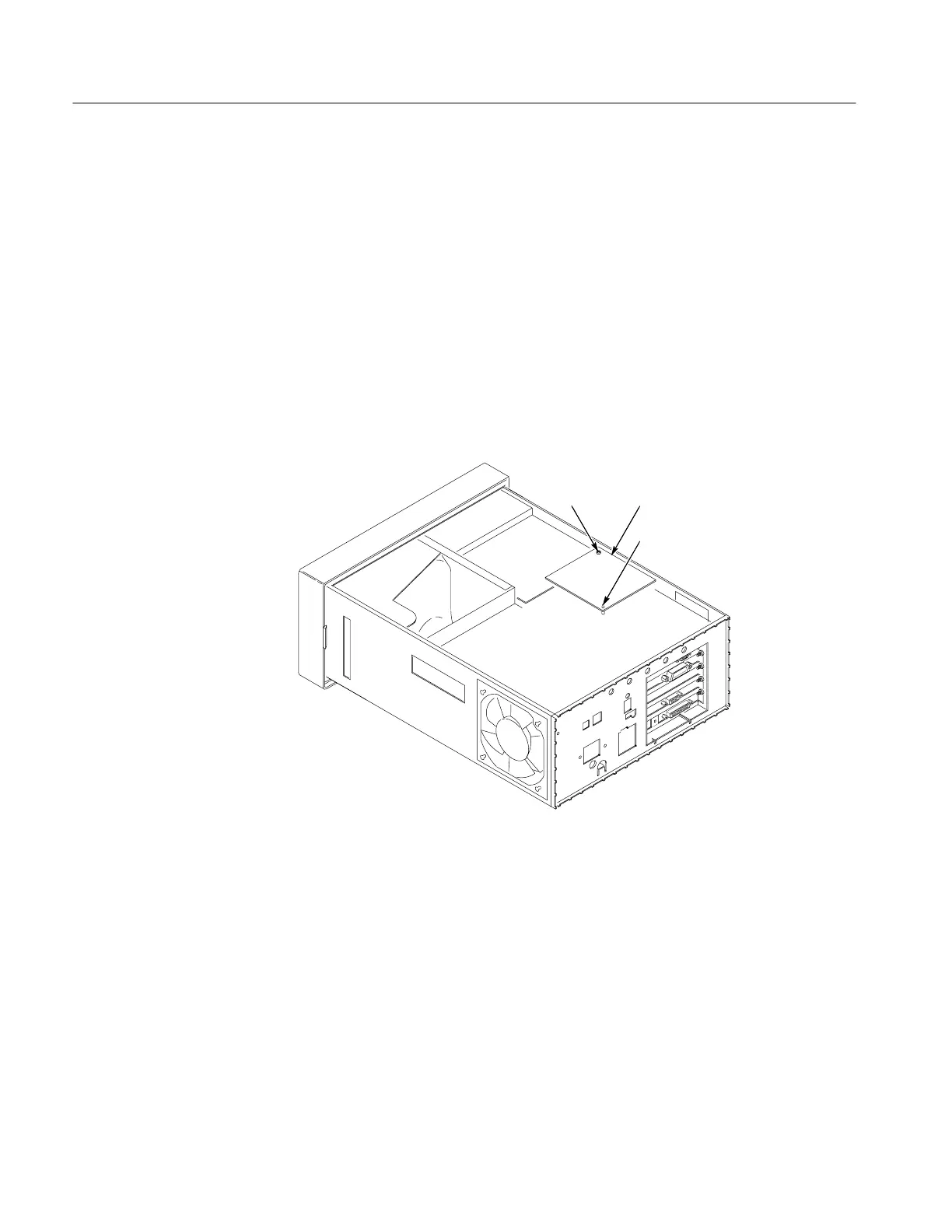
3. Remove the floppy interface board, shown in Figure 6–11, by removing the
screw, unclipping the standoff post from the board, and gently rocking the
board from side to side while lifting. Make sure that you lift and rock from
the connector end of the board.
Remove this
screw
Floppy interface board
Unclip post from board
Figure 6–11: Removing the floppy interface board
 Loading...


