Removal and Installation Procedures
TDS 520A, 524A, 540A, & 544A Service Manual
6Ć27
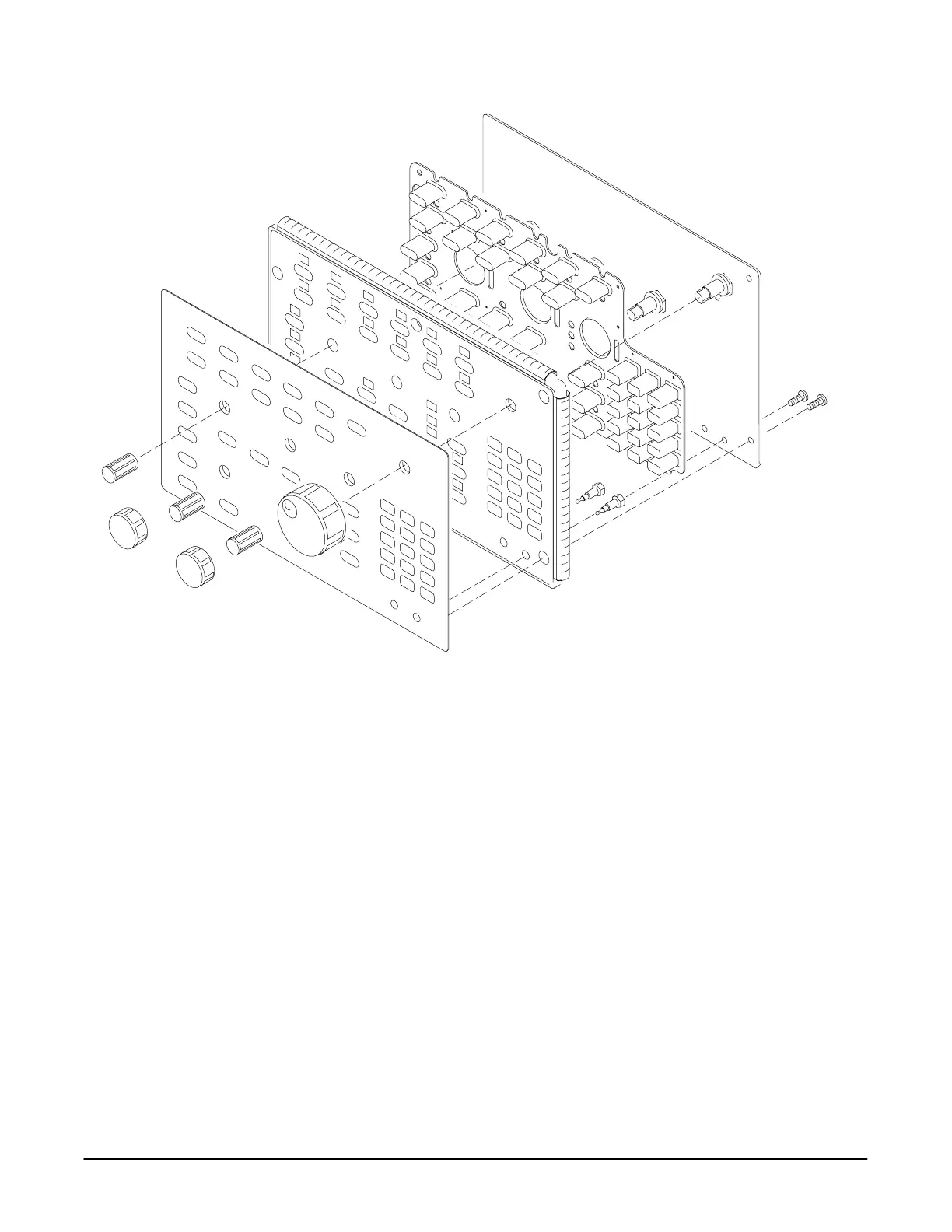
Figure 6Ć10:ăDisassembly of FrontĆPanel Assembly
Reinstallation: % #! %," $$* ($ &#%# $$$
$%" % #'#$ $&$%"$ %! #$$ &$ &# , $
& ! $%" #'#$ % "#!&# !&% $%"
$% # $% % %# # $# % #! % !'# ### %! %
"#!&# Front Cover, Trim Ring, Menu Buttons, and Attenuator Panel
" ,
DisplayĆFrame Assembly
Assemble equipment and locate modules to be removed: ' *
$#(#'# (% $+ , !#)R %$ !% % !&$ %!
#!' % !%!# # OuterĆChassis Modules &#,
" ,
Orient the oscilloscope: % % !$!$!" $! %$ !%%! $ !( ! %
(!# $&# %$ #! % $ *!&
Remove the displayĆframe assembly:
 Loading...


