Removal and Installation Procedures
TDS 520A, 524A, 540A, & 544A Service Manual
6Ć43
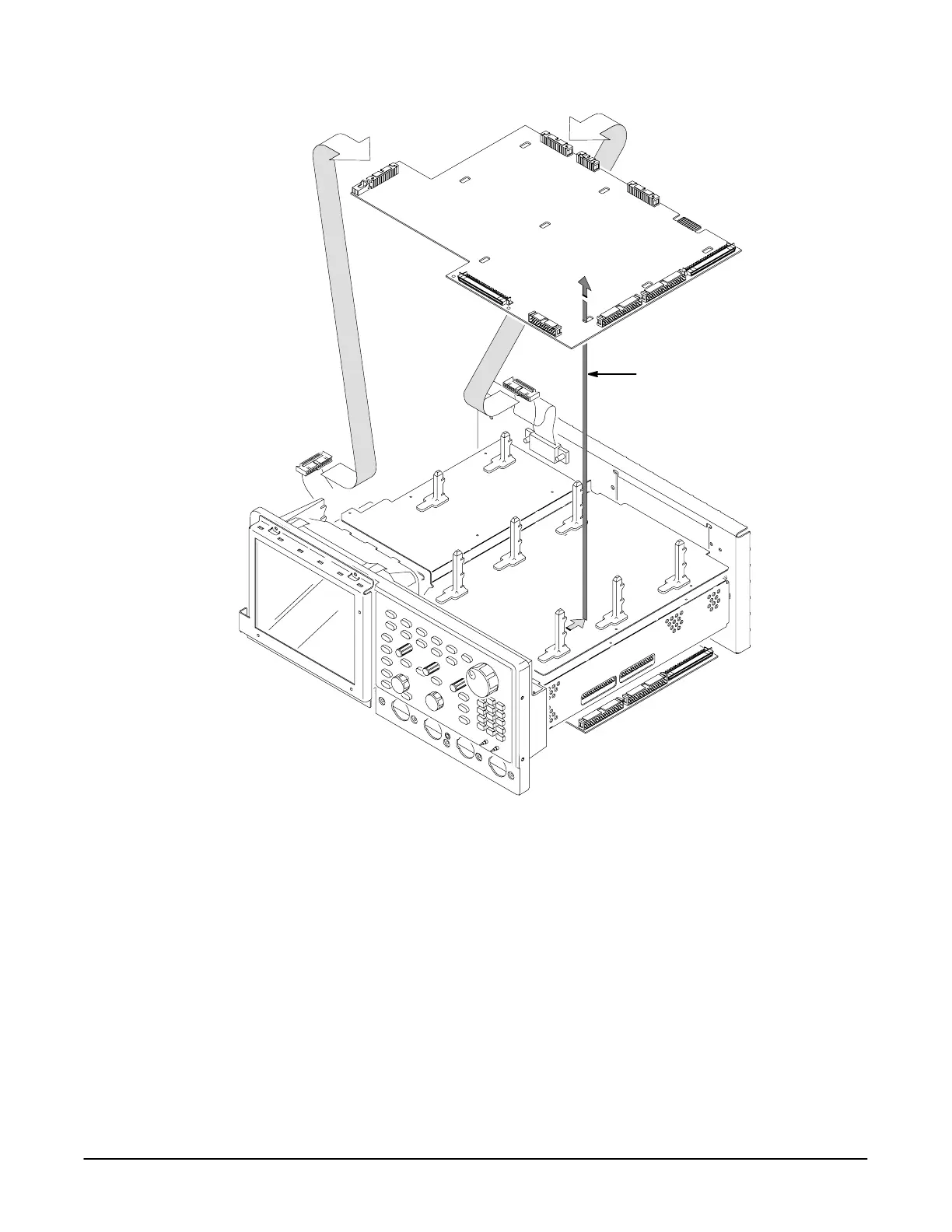
First, unplug the
cables at J38 and J35.
Second, slide the A11 DRAM
Processor/Display board to
the rear to release if from the
board mounts; then lift up to
complete removal.
J38
J35
Figure 6Ć19:ăA11 Processor/Display Removal
Top Cover and Board Brackets
Assemble equipment and locate modules to be removed:
" % #" # & ' $R
" % board mount ' #"
! " OuterĆ
Chassis Modules ! ' '
 Loading...


