Performance Tests
TDS 420A, TDS 430A & TDS 460A Service Manual
4-57
H Input the correction factor for the new frequency into the level meter.
H Adjust the sine wave generator amplitude until the level meter again
reads the value noted in step 3. The signal amplitude is now
correctly set for the new frequency.
Equipment
Required
Sine Wave Generator (Item 11)
Level Meter and Power Sensor (Item 12)
Two Male N to Female BNC Adapters (Item 15)
Two precision coaxial cables (Item 5)
Prerequisites See page 4--15.
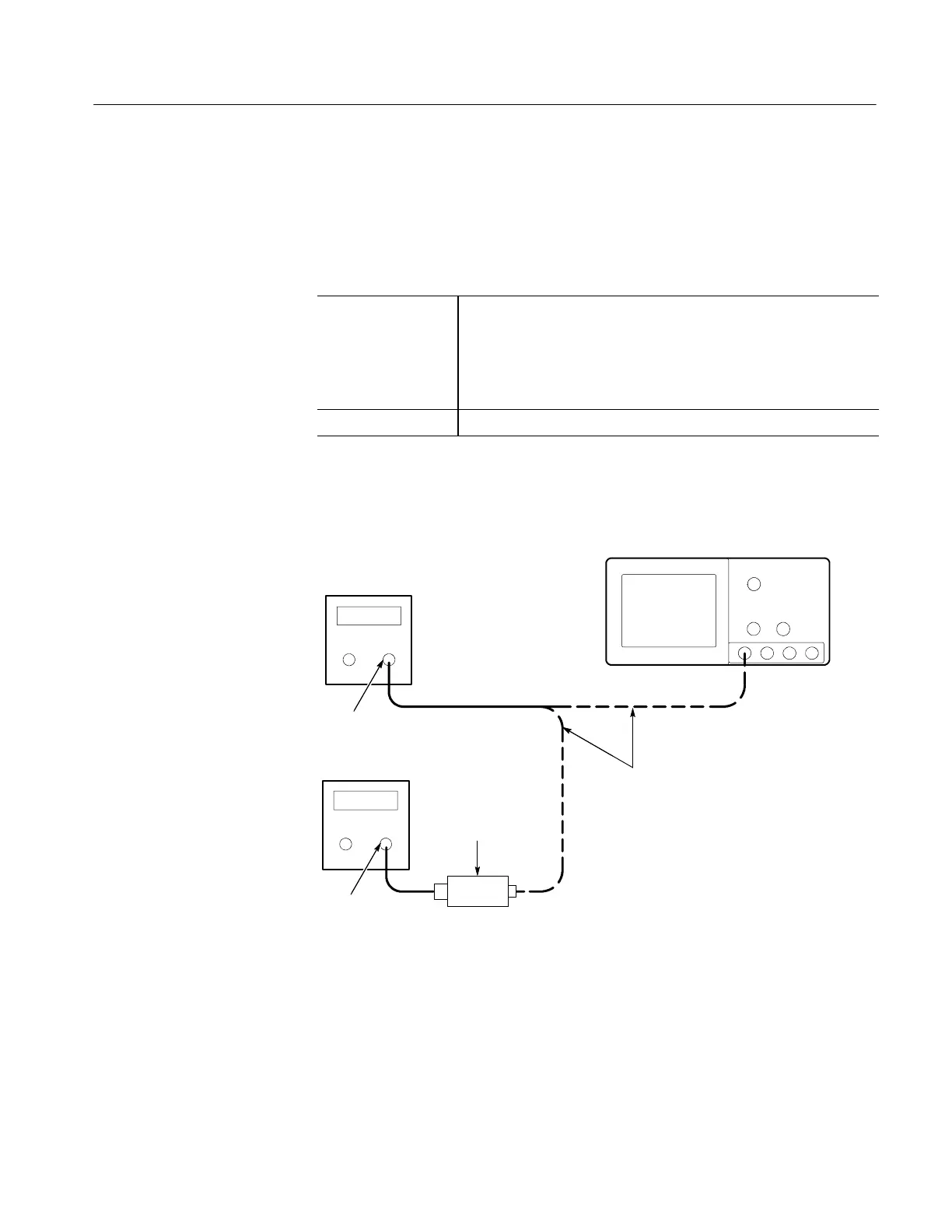
1. Install the test hookup: Connect the equipment as shown in Figure 4--24
(start with the sine wave generator connected to the digitizing oscilloscope).
Digitizing Oscilloscope
Level
Meter
Power
Sensor
Sine Wave
Generator
Output
Input
Connect the sine wave
generator to the
oscilloscope and the
power sensor as
directed in the text.
Figure 4- 24: Equipment Setup for maximum Amplitude
2. Set the Generator:
H Set the sine wave generator to a reference frequency of 10 MHz.
H Adjust the sine wave generator amplitude to the required number of
divisions as measured by the digitizing oscilloscope.
Alternate Procedure for
Maximum Amplitude

 Loading...


