Adjustment Procedures
5-16
TDS 420A, TDS 430A & TDS 460A Service Manual
Use a small standard screw driver to
pry between the cover and metal cord
connector to pop off cover.
Repeat for lower cover.
Figure 5- 6: Exposing the Probe Body
b. Hook up test-signal source:
H Connect the high-amplitude output of a pulse generator, through a
50 Ω precision cable to the input of the pulse generator head (see
Figure 5--7).
H Connect the output of the pulse generator head through a 10X
attenuator to CH 1.
H Set the triggering level of the pulse generator head to minimum.
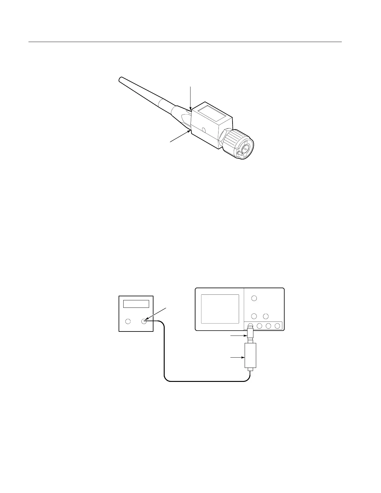
Pulse Generator
Digitizing Oscilloscope
Pulse Generator
Head
10X Attenuator
Precision Cable
Output
Figure 5- 7: Initial Test Hookup
c. Initialize the oscilloscope:
H Press save/recall SETUP.

 Loading...


