Troubleshooting
6-94
TDS 420A, TDS 430A & TDS 460A Service Manual
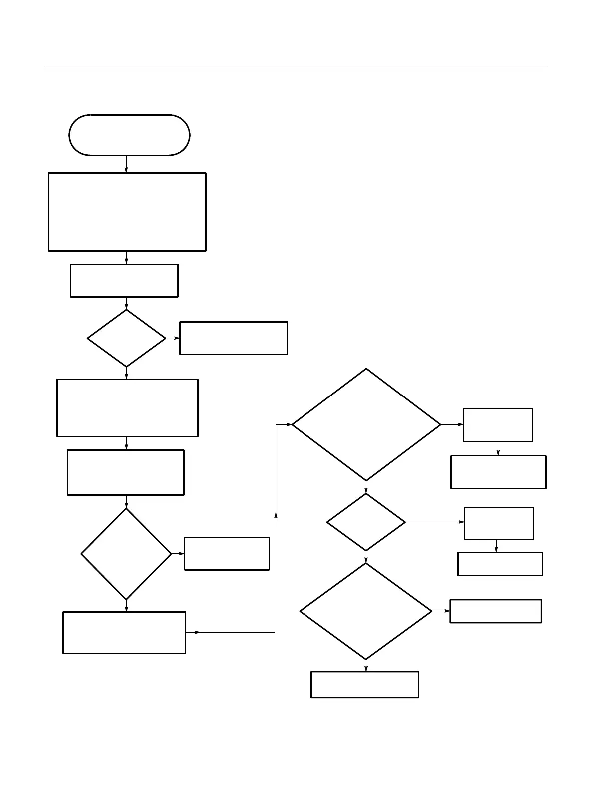
Figure 6- 45: Attenuator/Acquisition Troubleshooting Procedure
Are
pins 26,
27, and 29 of
P1 (see Figure 6--46)
about
400 mV 1 k Hz
square
waves?
Yes
No
No
Yes
Use this procedure to
isolate a problem between the
A04 Acquisition, A08 Jumper, and
A05 Attenuator boards.
This procedure assumes that the oscillos cope is
not displaying or not triggering properly on one or
more channels. It also assumes that the power-up
diagnostic fails with FAIL++Acq, FAIL++Attn,
FAIL++Cpu/Acq..., or FAIL++Acq/Attn messages.
This procedure is for CH 1, but you can us ed it for
all four input channels by substituting the
appropriate data from Table 6--14.
Is the power
ok?
Perform the Acquisition and
Attenuator Power troubleshooting
procedure.
Perform the Low Voltage Power
Supply troubleshooting
procedure.
Attach a X10 probe to the CH 1 input.
Attach the probe tip to the PROBE ADJUST
connector on the front panel. Set the trigger
source to CH1, and press AUTOSET. Set
the Vertical SCALE to 10 mV.
Set your bench oscilloscope to
500 s per division, 200 mV per
division, bandwidth limit to 20 MHz,
and AUTO trigger.
The tested channel
of the A05 Attenuator
board is ok.
Repeat this procedure for
each input channel.
Using the A08 J umper Board Assembly,
D1 Bus, and Board Supports removal
procedure (see page 6--44), remove the
A08 Jumper board.
Perform the I2C
troubleshooting
procedure.
Are the signals
not visible at
all?
Before
removing the
A08 Jumper board were
the signals double the amplitude,
and are they
still double the
amplitude?
Replace the A04 Acquisition board
or the A08 J umper board.
Yes
No
Yes
No
Are the
CH1 Trigger, CH1
Vertical, and CH1 Vertical inverted
signals on J102 pins 26, 27, and 28
of the A05 Attenuator board about
100 mV 1 k Hz
square waves?
Yes
No
Replace the A04 Acquisition
board or the A08 Jumper
board.
Replace the
A05 Attenuator board.
Perform the I2C
troubleshooting
procedure.

 Loading...


