Troubleshooting
6-98
TDS 420A, TDS 430A & TDS 460A Service Manual
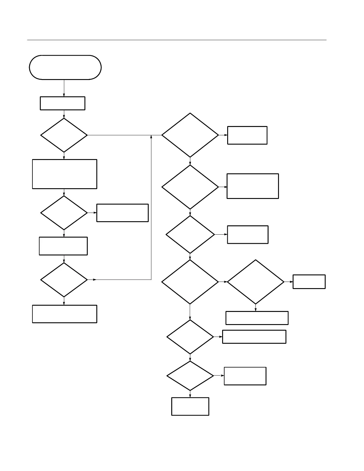
Figure 6- 49: Backplane Tr oubleshooting Procedure
Replace the
A01 Backplane
module.
Perform the A25 Low
Voltage Power Supply
troubleshooting procedure.
Yes
No
Yes
No
No
Yes
Use this procedure to
troubleshoot the A01 Backplane
board.
Press the ON/STBY
button.
Does the
oscilloscope
power up?
Does the
oscilloscope power
up?
Disconnect P2 (between the
A07 Auxiliary Power and A25 Low
Voltage Power Supply m odules).
Press the ON/STBY button.
Replace the A25 Low
Voltage Power Supply
board.
Reconnect P2. Press
the ON/STBY button.
Does the
oscilloscope power
up?
Yes
No
Replace either the A06 Front Panel,
A01 Backplane, or A07 Auxiliary
Power boards.
Are the
voltages at U1--U4 ok
(see Table 6--17 and
Figure
6--50)?
Replace the
A01 Backplane
module.
Are the
voltages at J7
ok (see Table 6--18 and
Figure 6--50)?
No
Yes
There is not a problem
with the
A01 Backplane.
Are the
voltages at J8 ok
(see Table 6--19)?
Does
one of the
plug-in boards not
work, but the other
boards
do?
Does the
bad board
work in another
A01 Backplane slot?
Replace the A01 Backplane
module.
Replace the bad
board.
Are there
intermittent
problems?
Replace the A01 Backplane
module.
Are
there still
problems?
Replace the
A01 Backplane
module.
Yes
No
Yes
No
No
Yes
No
Yes
No
Yes

 Loading...


