Typical Characteristics
1-24
TDS 420A, TDS 430A & TDS 460A Service Manual
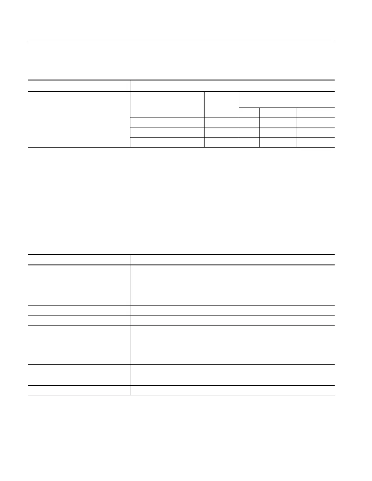
Table 1- 17: Typical Characteristics — Signal Acquisition System (Cont.)
Name Description
Step Response Settling Error Volts/Div Setting Step Ampli-
tude
Settling Error (%)
4
20 ns 500 ns 20 ms
1 mV/div--99.5 mV/div ≤2V ≤0.5 ≤0.2 ≤0.1
100 mV/div --995 mV/div ≤20 V ≤2.0 ≤0.5 ≤0.2
1 V/div--10 V/div ≤200 V ≤2.0 ≤0.5 ≤0.2
1
Net Offset = Offset - (Position x Volts/Div). Net Offset is the voltage level at the center of theA-D converterdynam ic
range. Offset Accuracy i s the accuracy of this vol tage level .
2
The sampl es must be acqui red under the same setup and ambi ent condi ti ons.
3
A DL (digitizati on level) is the smallest voltage level change that can be resolved by the 8-bit A-D Converter with the input
scaled to the volts/division setting of the channel used. Expressed as a voltage, a DL is equal to 1/25 of a division times
the volts/division setting.
4
The values given are the maximum absolute difference between the value at the end of a specified time interval after the
mid-l evel crossing of the step and the value one second after the mid-level crossing of the step, expressed as a
percentage of the step amplitude.
Table 1- 18: Typical Characteristics — Time Base System
Name Description
Aperture Uncertainty For real-time or interpolated records having duration ≤1 minute:
≤(50 ps + 0.03 ppm × Record Durati on) RMS
For equivalent time records:
≤(50 ps + 0.06 ppm × WI
1
)RMS
FixedErrorinSampleTime ≤50 ps
External Clock sampling uncertainty ±8ns
External Clock Edge to Sampling Time
Delay
Sample --20 ns (Sample edge is delayed rel ative the the sample moment.)
Hi Res Hi Res averaging starts within 8 ns of the clock edge.
Averaging stops after 1/(maximum external clock rate
2
)
Peak Detect Runs continuously at 100 MS/s
External Clock Minimum Prerecord points 55 points before the first visible sample in the record at the maximum clock speed
35 points before the first visible sample in the record at slow clock speeds
External Clock Minimum Postrecord points 25 points after the last visible sample in the record
1
The WI (waveform interval) is the tim e between the samples in the waveform record. Al so, see the footnotes for
Sample Rate Range and Equi valent Time or Interpolated Waveform Rates in Table 1 - 4 on page 1 - 9.
2
You set the m aximum external cl ock rate using the Horizontal Clock menu.

 Loading...


