Adjustment Procedures
5–12
TDS 500B, 600B and TDS 700A Service Manual
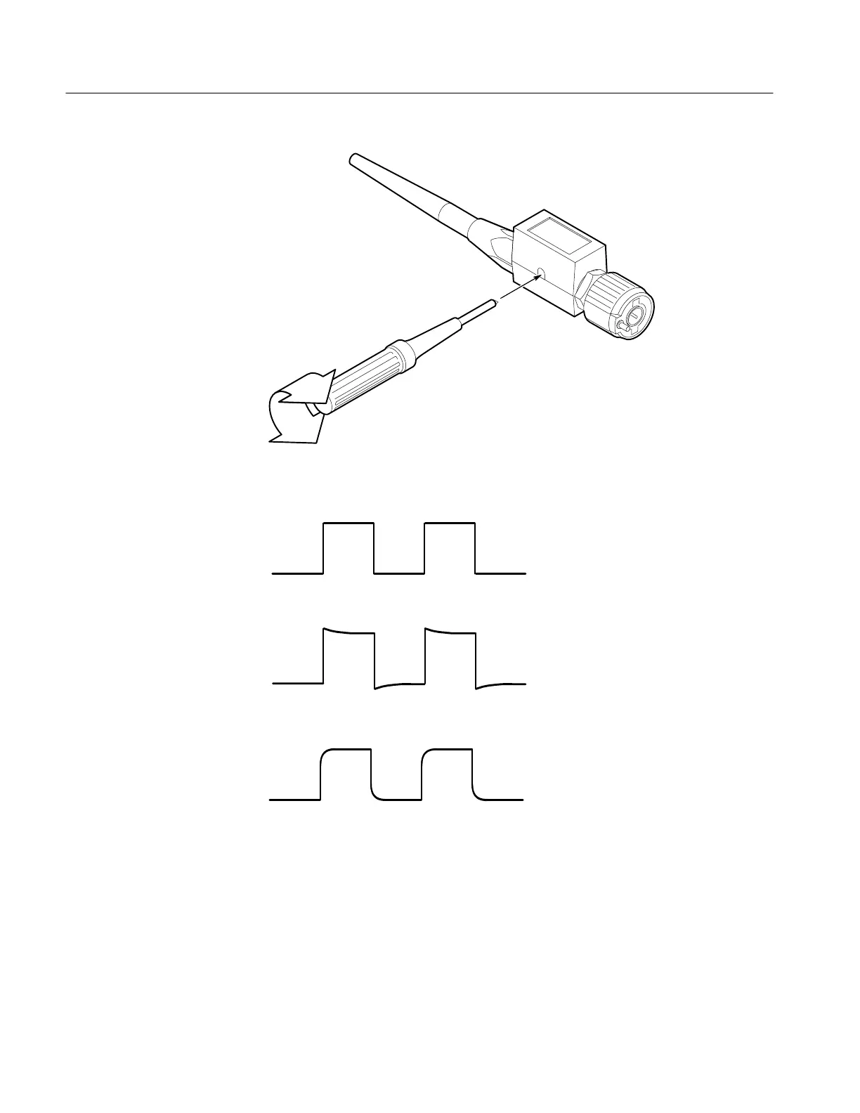
Figure 5–3: Performing Probe Compensation
Probe compensated correctly
Probe overcompensated
Probe undercompensated
Figure 5–4: Proper and Improper Probe Compensation
3. Disconnect the hookup: Disconnect the probe from the probe compensator
terminals; leave probe installed on CH 1 and leave the oscilloscope control
setup as is for doing the next part of probe adjustment.
 Loading...


