Adjustment Procedures
TDS 500B, 600B and TDS 700A Service Manual
5–21
Display Assembly Adjustment
STOP. It is not necessary to do this procedure to perform a complete adjustment.
Only use this procedure to adjust the display assembly if it has been repaired or
if brightness and contrast have become unsatisfactory.
Equipment
Required
One 6X magnifier (Item 15)
One J16 Photometer with a J6503 Luminance Probe (Item 16)
1. Access the inside of the oscilloscope: See Removal and Installation
Procedures in Section 6 to remove the cabinet.
2. Adjust the display brightness:
a. Display the Composite test pattern:
H Leave the oscilloscope powered off.
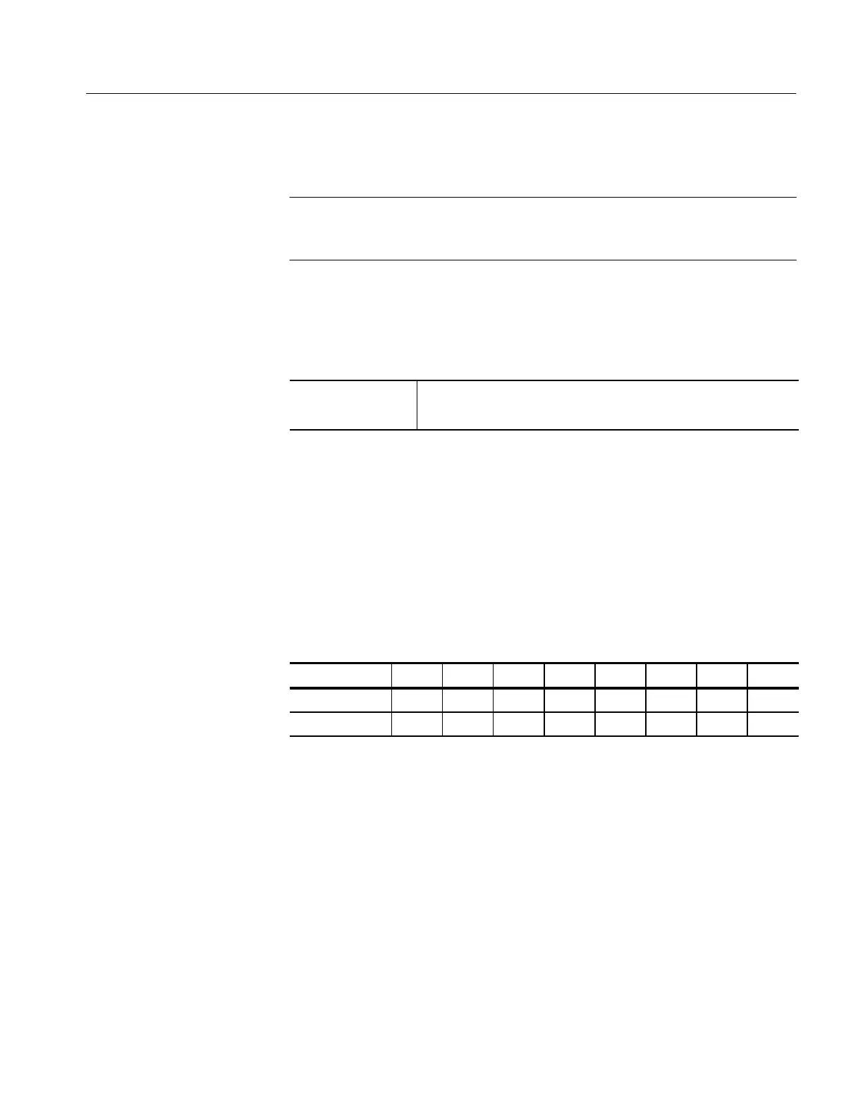
H Set the DIP switch, located near the front of the A11 DRAM
Processor/Display, as follows:
Switch No. 1 2 3 4 5 6 7 8
Open X X
Closed X X X X X X
H Power on the oscilloscope.
H Press SHIFT; then press UTILITY.
H Repeatedly press the main-menu button System until Diag/Err is
highlighted in the pop-up menu.
H Repeatedly press the main-menu button Area until Display is
highlighted in the pop-up menu.
H Repeatedly press the side-menu button –more– until Composite
appears in the side menu. Push Composite.
H Press the main-menu button EXECUTE; then press the side-
menu button Ok Confirm Run Test.
Brightness, and Contrast
Adjustment
(TDS 500B, 620B and
680B – Monochrome Only)
 Loading...


