Adjustment Procedures
5–24
TDS 500B, 600B and TDS 700A Service Manual
Equipment
Required
One 6X magnifier (Item 15)
One J16 Photometer with a J6503 Luminance Probe (Item 16)
1. Access the inside of the oscilloscope: See Removal and Installation
Procedures in Section 6 to remove the cabinet.
2. Adjust the display rotation:
a. Display the Composite test pattern:
H Leave the oscilloscope powered off.
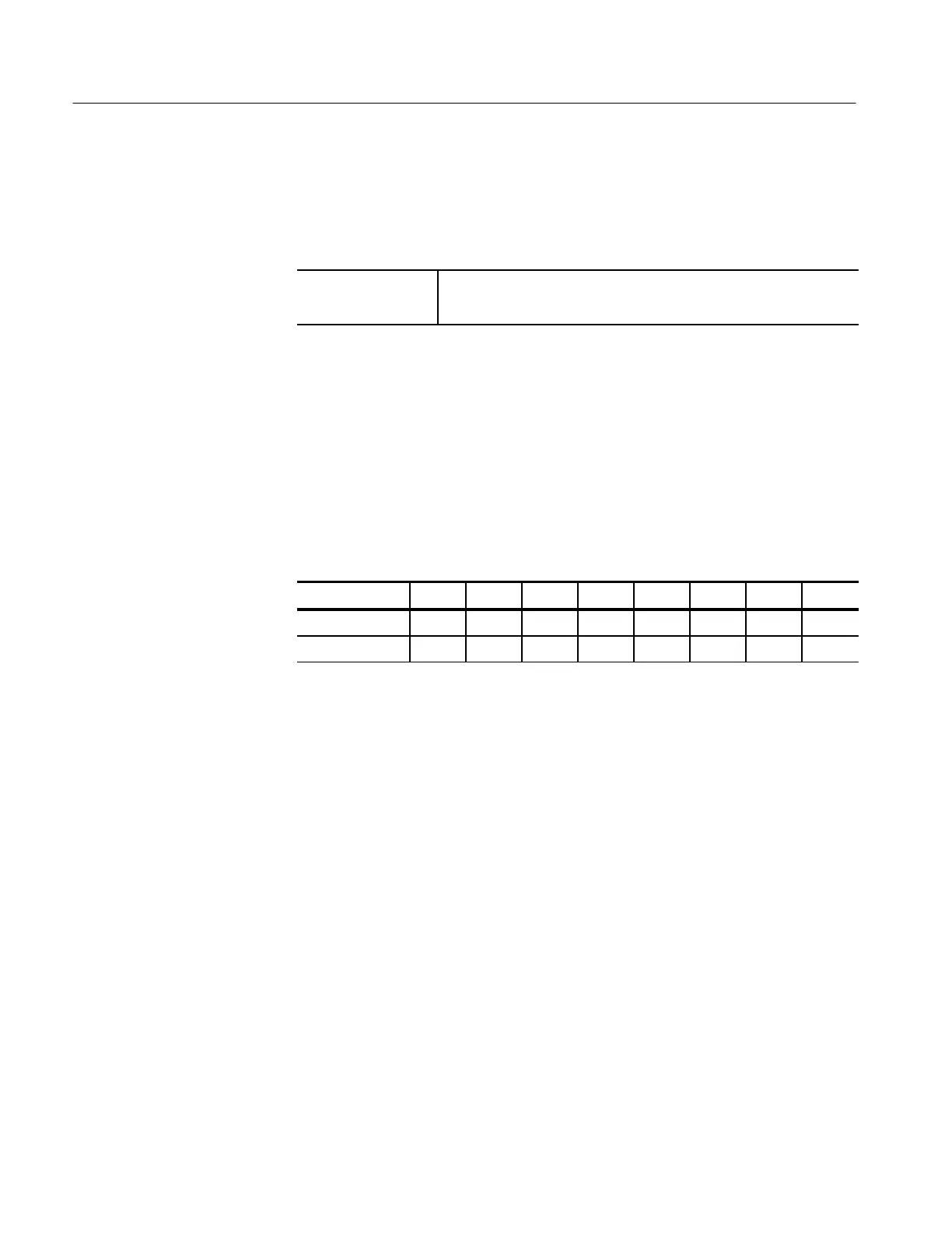
H Set the DIP switch, located near the front of the A11 DRAM
Processor/Display, as follows:
Switch No. 1 2 3 4 5 6 7 8
Open X X X
Closed X X X X X
H Power on the oscilloscope.
H Press SHIFT; then press UTILITY.
H Repeatedly press the main-menu button System until Diag/Err is
highlighted in the pop-up menu.
H Repeatedly press the main-menu button Area until Display is
highlighted in the pop-up menu.
H Repeatedly press the side-menu button –more– until Composite
appears in the side menu. Push Composite.
H Press the main-menu button EXECUTE; then press the side-
menu button Ok Confirm Run Test.
b. Adjust R401 (TRACE ROTATION) to minimize the display’s tilt. Use
the frame around the display as a reference. R401 is the second
adjustment from the fan.
3. Adjust the display brightness:
Rotation, Brightness, and
Contrast Adjustment
(TDS 644B, 684B, and
700A – Color Only)
 Loading...


