Getting Acquain
tedwithYourInstrument
VM5000 / TDS500 0 Series Instrument
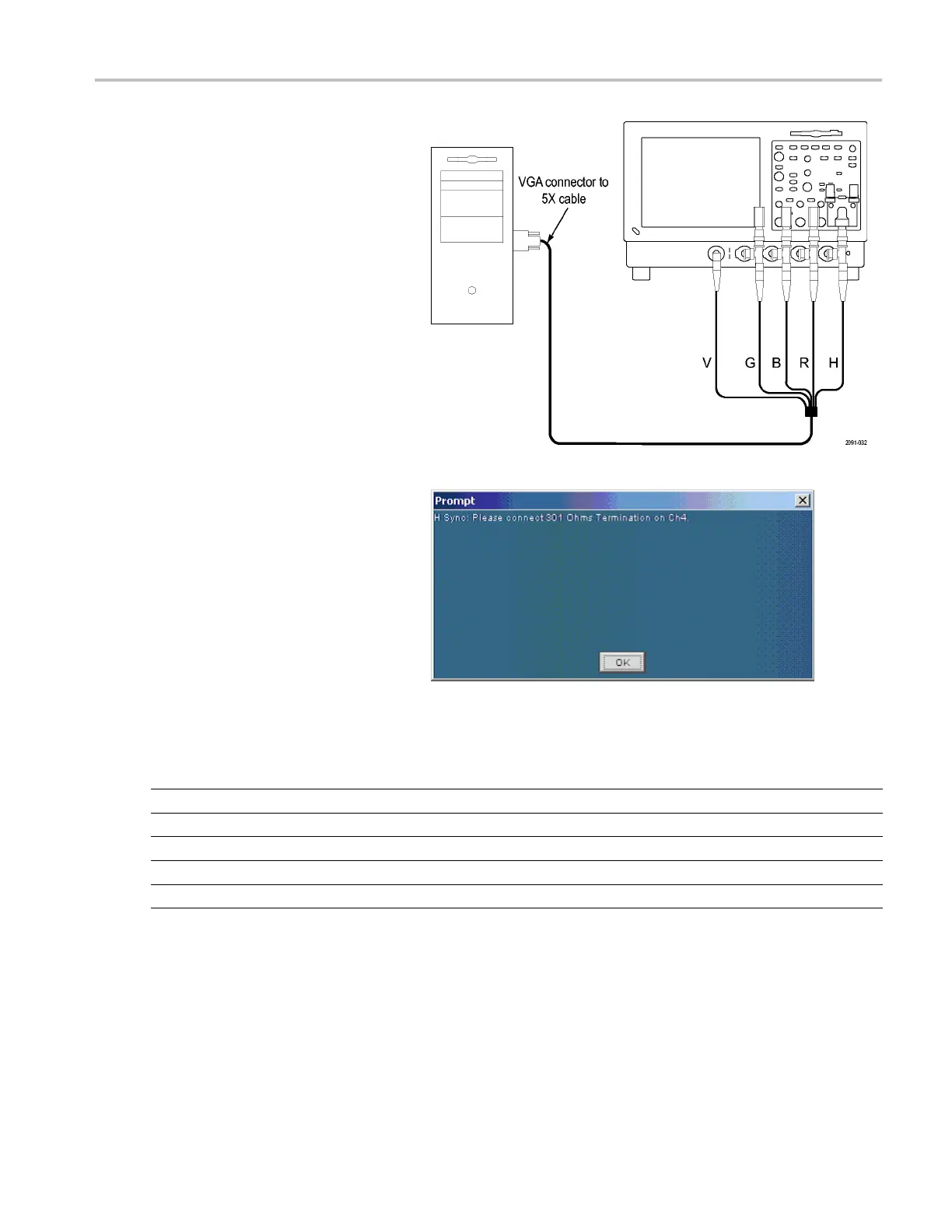
A pop-up warning prompts you to change
signal termination on CH4 when making an
H Sync measurement.
The following table identifies which s ignal from the DUT should be connec ted to which input connector on the VM Series
system and which termination should be used for each signal.
VGA signal VM Series system input connector Termination
Green CH 1 75 Ω
Blue
CH 2 75 Ω
Red
CH 3 75 Ω
HSync CH4
1
2.21 kΩ and 301 Ω
VSync
AUX None
1
VSync
signal is connected to this channel when making a V Timing or V Sync measurement. The V M Series system will prompt you for this
connection change if necessary.
VM Series Video Measurement System Quick Start User Manual 19
 Loading...


