Performance Tests
TDS7104 & TDS7054 Service Manual
4-77
H CHECK that the readout CH 2 Pk-Pk is between 44 mV and 66 mV,
inclusive.
H Enter voltage on test record.
4. Disconnect the hookup: Disconnect the cables from the channel inputs and
the rear panel outputs.
Equipment
required
Two dual-banana connectors (Item 6)
One BNC T connector (Item 7)
Two precision 50 Ω coaxial cabl es (Item 4)
One DC calibration generator (Item 9)
Prerequisites See page 4--27. Also, the oscilloscope must have passed Check
Long-Term Sampl e Rate and Delay Time Accuracy and Reference on
page 4--57.
1. Install the test hookup and preset the instrument controls:
a. Hook up test-signal:
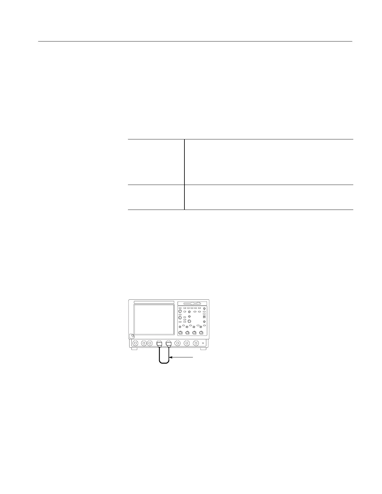
H Connect one of the 50 Ω cables to CH 1. See Figure 4--35.
H Connect the other end of the cable just installed to the PROBE
COMPENSATION input. See Figure 4--35.
TDS7000 oscilloscope
BNC cable from PROBE
COMPENSATION output
to CH 1 input
Figure 4- 35: Initial test hookup
b. Initialize the oscilloscope: Press the DEFAULT SETUP button.
c. Modify the initialized front-panel control settings:
H Set the Vertical SCALE to 200 mV.
Check Probe
Compensation Output
 Loading...
