Performance Tests
TDS7104 & TDS7054 Service Manual
4-79
H Touch the Save Wfm to Ref1 Save button to save the probe
compensation signal in reference 1.
H Disconnect the cable from CH 1 and the probe compensation
connector.
H Touch the Display button to toggle it to on to displayed the stored
signal.
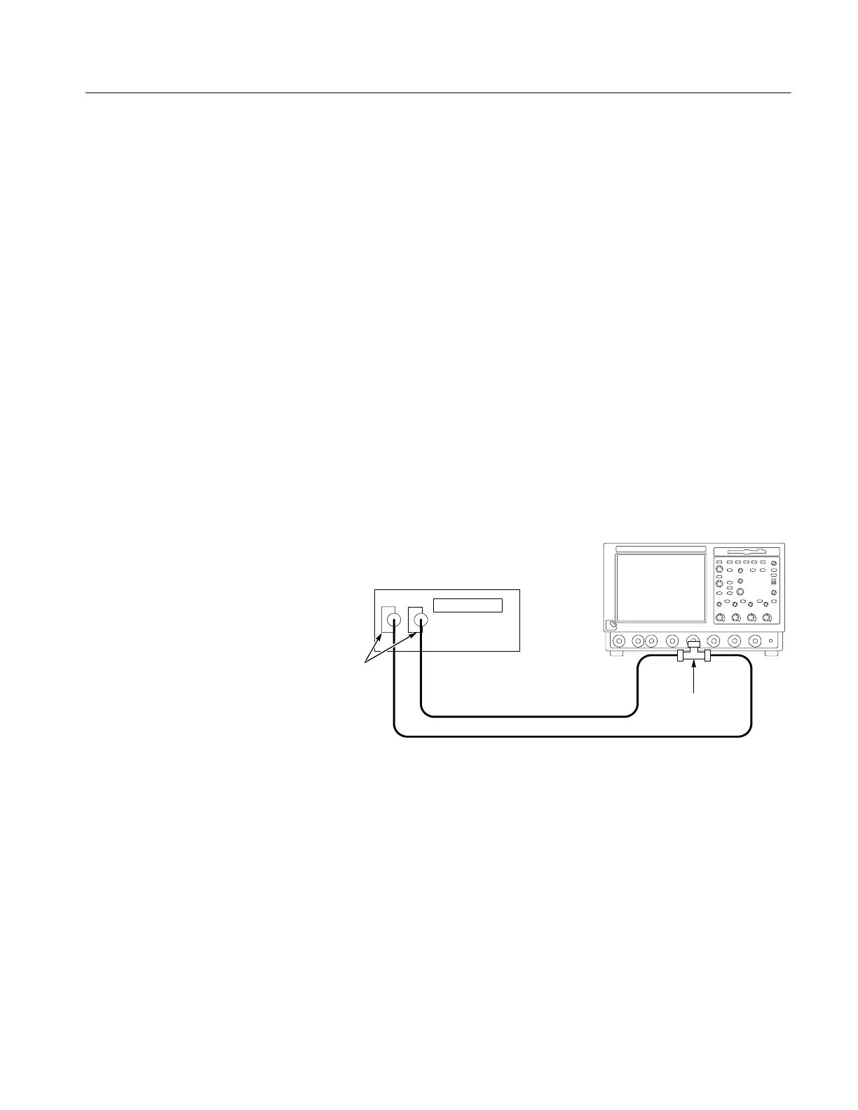
d. Hook up the DC standard source:
H Set the output of a DC calibration generator to off or 0 volts.
H Connect the output of a DC calibration generator through a
dual-banana connector followed by a 50 Ω precision coaxial cable to
one side of a BNC T connector. See Figure 4--37.
H Connect the Sense input of the generator through a second dual-ba-
nana connector followed by a 50 Ω precision coaxial cable to the
other side of the BNC T connector. Now connect the BNC T
connector to CH 1. See Figure 4--37.
TDS7000 oscilloscope
DC calibrator
50 Ω coaxial cables
Dual banana to
BNC adapters
BNC T
connector
Figure 4- 37: Subsequent test hookup
e. Measure amplitude of the probe compensation signal:
H From the tool bar, touch Horiz and select the Acquisition tab.
H Touch Average and set the number of averages to 16 using the
keypad or the multipurpose knob.
H Adjust the output of the DC calibration generator until it precisely
overlaps the top (upper) level of the stored probe compensation
signal. (This value will be near 1000 mV).
 Loading...
