Adjustment Procedures
TDS7104 & TDS7054 Service Manual
5-5
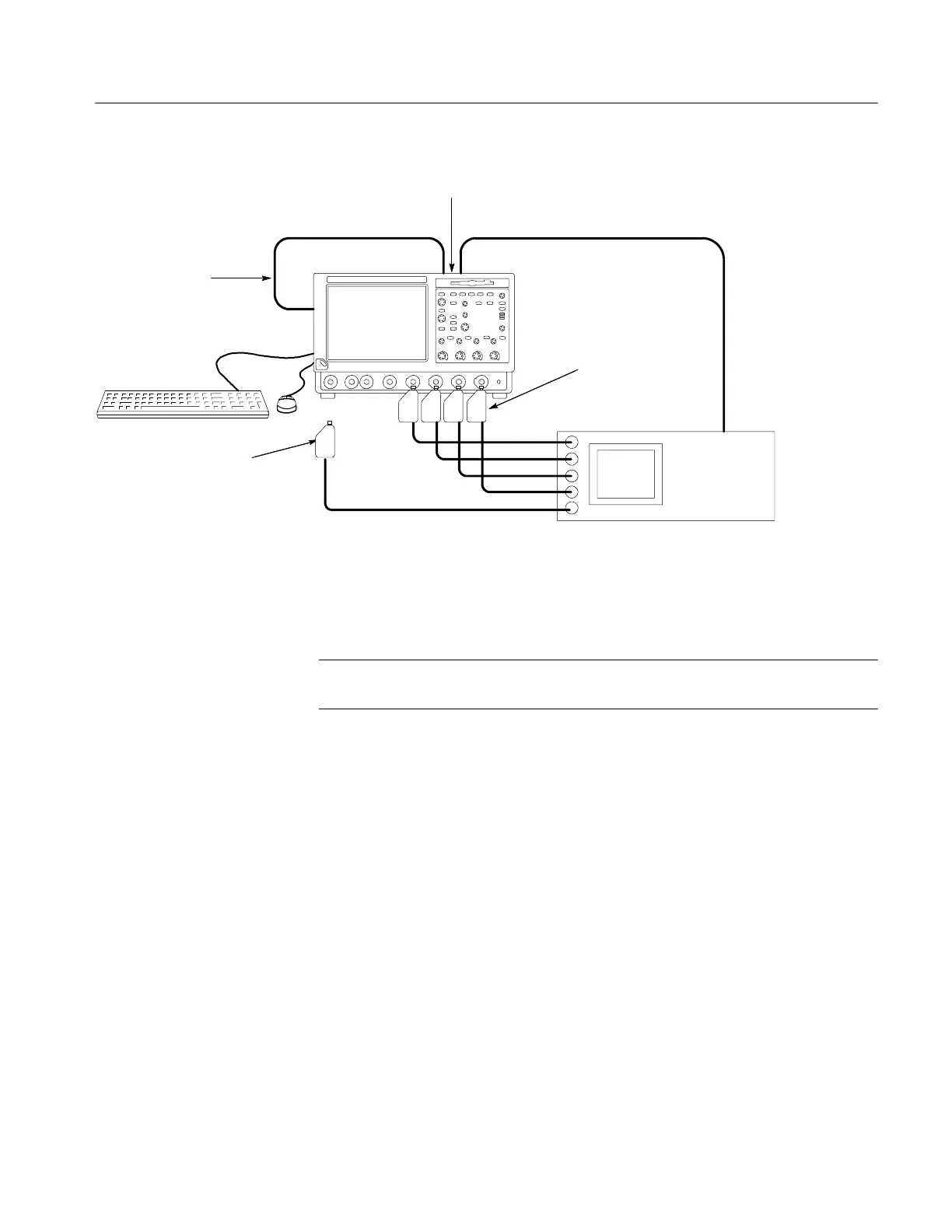
Fluke 9500B
Oscilloscope
GPIB cable
GPIB cable from
PCMCIA or USB
GBIP card
GPIB cables daisy chained onto
the oscilloscope GPIB connector
GPIB cable
Connect Fluke 9520 or
9530 output modules
to the oscilloscope
CH1 through CH 4
inputs as shown
Connecting the fifth output
module to the oscilloscope is
only required when prompted
to connect the head by the
adjustment program
Figure 5- 2: Adjustment setup using the oscilloscope as the controller
Once the connections have been made, follow these steps:
NOTE. If you have just completed the performance verification procedure, you
can skip all the following steps in this setup procedure.
1. Power on the instruments: Turn power for the controller, oscilloscope, and
signal source on. The oscilloscope and the signal source must warm up for
20 minutes before you can begin to execute the test. However, while you are
waiting you can continue with the next steps in this procedure.
2. Check the Fluke 9500B GPIB address: Refer to the Fluke 9500B documenta-
tion for information about setting the GPIB address. If the address is set to 0
or 1, change it to an address between 2 and 30 (inclusive). Make a note of
the address setting for use later in this procedure.
3. Set the GPIB address of the oscilloscope.
a. If the oscilloscope powered on in the toolbar mode (the default mode),
click the Menu button (upper right corner of the display) to put the
oscilloscope in menu-bar mode. In menu-bar mode, you should then see
a PC-style menu bar across the top of the display.
b. Pull down the Utility menu and then select GPIB Configuration . . . .
This command will display the GPIB Configuration control window.
 Loading...
