Removal and Installation Procedures
6-- 34
TDS7104 & TDS7054 Service Manual
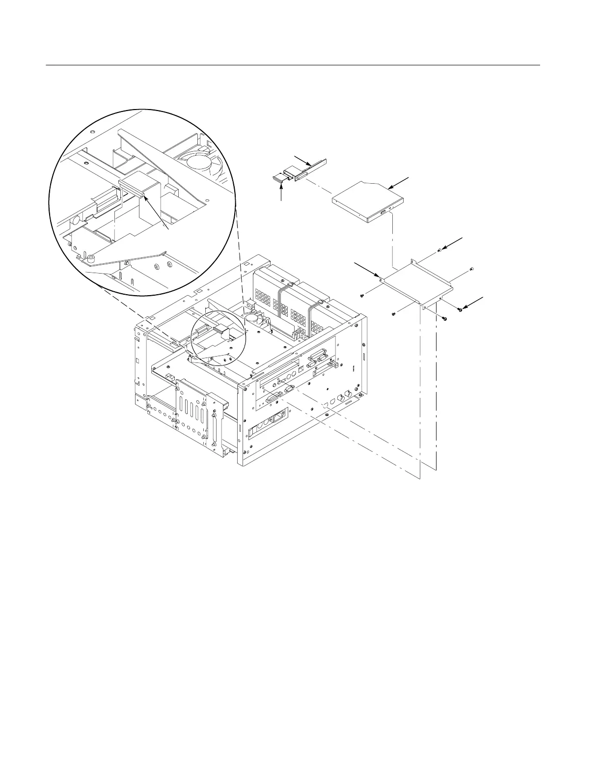
CD drive
interface board
CD drive
#0 Phillips
screw (4)
CD drive bracket
CD drive
ribbon cable
Disconnect
J230 CD drive
ribbon cable
T--15 Torxdrive
screw (2)
Figure 6--20: CD drive and bracket removal
1. Locate module to be removed: Locate the Fan assembly in the locator
diagram Internal Modules, Figure 6--8, on page 6--19. Additional modules to
be Removed:
H Trim (all)
H Bottom cover
H Left and Right covers
2. Orient the oscilloscope: Set the oscilloscope so its bottom is down on the
work surface and its left side is facing you.
3. Remove the fan: See Figure 6--21, on page 6--35.
Fan Assembly Removal
 Loading...
