Troubleshooting
TDS7104 & TDS7054 Service Manual
6-- 55
If the mains power switch is on and the oscilloscope is not on, (power supply is
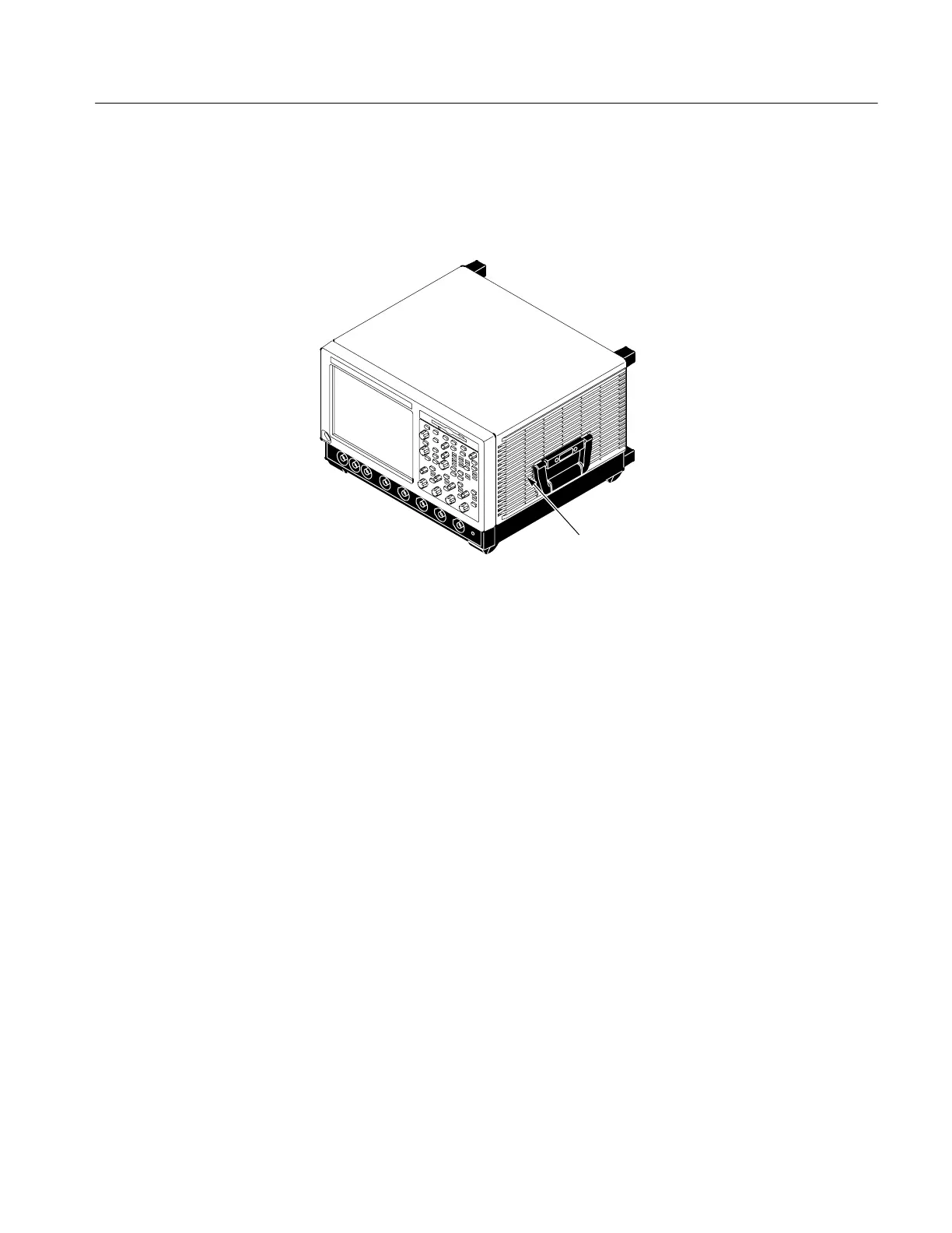
in standby mode), a red light (see Figure 6--31 for its location) is visible through
the right side of the oscilloscope. If the oscilloscope is on, the red light is off.
Mains power-on and over current LEDs are
near the center of the power supply. A red
glow from them is visible while looking
through the side of Oscilloscope
Figure 6--31: Location of power-on and over current LEDs
If the oscilloscope thinks power is on, a red light (see Figure 6--31) means that
there is an over current condition.
If the on/standby pin (pin C1 of P201 on the rear power distribution board or pin
B162 on the riser board) is low, the oscilloscope thinks power is on.
Remove boards one at a time to locate a fault (the display, floppy, acquisition
board, front [analog supply to acquisition board] and power distribution board,
the NLX board, and the riser board). If you remove the NLX board, you must
jumper the debug power-on pins (see Figure 6--32). The PPC board and the rear
power distribution board are required for power to come up.
If removing the boards did not find the problem, replace the power supply.
Isolating to a Board if
Power Will Not Come Up
 Loading...
