Getting Acquain
ted with Your Instrument
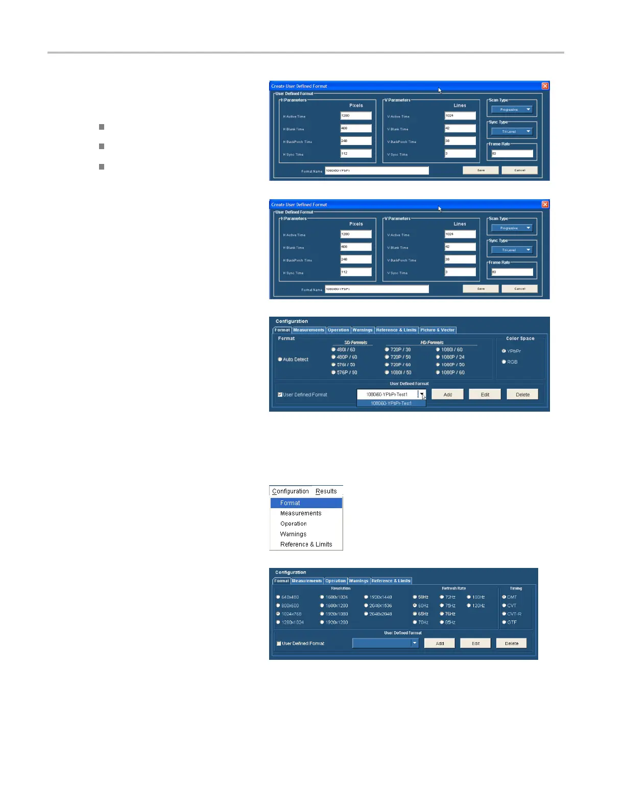
3. Enter values for both the horizontal and
vertical parameters that specify your
format.
SettheScanTyp
e.
Set the Sync Typ
e.
Enter a value f
or the Frame Rate.
4. Enter a format name and select Save to
save the new format.
5. TouseaUserDefined Format, check the
User Defined Format checkbox on the
Format tab
. Select the desired format
from the list box.
Setting the Input Signal Format – Option VGA
1. Select Configuration > F ormat.
The application displays the Format tab
view.
34 VM Series Video Measurement System Quick Start User Manual