12
E
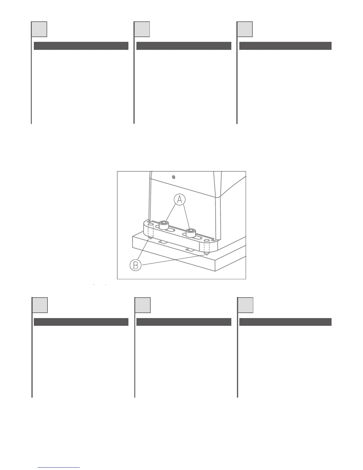
Appoggiare il motoriduttore sulla piastra
precedentemente fissata al basamento,
avvitare le 4 vitiA vedi fig 10. Prima di avvitare a
fondo le 4 vitiA, è possibile regolare la distanza
del motore dalla cremagliera agendo nei grani
B indicati sempre in fig. 10. In seguito è
importante bloccare energicamente le 4 viti A.
assicurandosi che durante tutta la corsa del
cancello,ilmotoriduttoresiabensaldoaterra.
Poser l'opérateur sur la plaque précédemment
fixée à la base, visser les 4 vis A (voir fig. 10).
Avant de visser à fond les 4 vis A, il est possible
de régler la distance du moteur par rapport à la
crémaillère en agissant sur les goujons B
indiqués eux aussi dans la fig. 10. Ensuite, il est
importer de serrer à fond les 4 vis A, en
contrôlant que durant toute la course du portail,
l'opérateurestbienfixéausol.
Apoye el motorreductor sobre la placa
precedentemente fijada a la bancada, atornille
los 4 tornillos A (véase la fig 10). Antes de
atornillar a fondo los 4 tornillos A, es posible
regular la distancia del motor de la cremallera
accionandolosbulonesdecentraje B indicados
siempre en la fig. 10. A continuación es
importante bloquear enérgicamente los 4
tornillosAasegurándose de que durante todo el
recorrido de la cancela el motorreductor se
encuentrebiensujetoalsuelo.
GB
D NL
Place the gearmotor onto the plate that was
previously fixed to the base and tighten the 4
bolts A (see fig. 10). The distance of the
gearmotor from the rack can be adjusted by
means of the dowels B illustrated in Fig. 10,
before fully tighteningthe four boltsA.After this
has been done, the 4 bolts A must be fully
tightened, making sure that the gearmotor is
firmly secured to the ground while the gate is in
motion.
Den Antrieb auf der vorher am Fundament
befestigten Platte mit den 4 Schrauben A
befestigen – siehe Abb. 10. Bevor die 4
Schrauben A festgezogen werden, kann der
Abstand zwischen Antrieb und Zahnstange
durch Betätigung der Stifte, angegeben in Abb.
10, reguliert werden. Wichtig: die 4 SchraubenA
danach energisch festziehen und sicherstellen,
dass der Antrieb während des Torlaufs fest mit
demBodenverankertbleibt.
Zet de reductiemotor op de plaat die u
daarvoor op de grondplaat hebt bevestigd,
draai de 4 schroeven A van afb. 10 aan.
Voordat u de 4 schroeven A helemaal vast
draait, is het mogelijk de afstand van de motor
ten opzichte van de tandheugel af te stellen,
waarvoor u de stiften B op afb. 10. gebruikt.
Vervolgens is het van belang de 4 schroevenA
stevig vast te draaien waarbij u zich ervan
dient te vergewissen dat de reductiemotor
over de gehele loop van de poort goed vast zit
opdegrond.ne.
F
I
Fig. 10 - Abb. 10
FIXING OF THE GEARMOTOR
BEFESTIGUNG DES ANTRIEBS
BEVESTIGING VAN DE REDUCTIEMOTOR
FISSAGGIO DEL MOTORIDUTTORE FIXATION DE L'OPÉRATEUR FIJACIÓN DEL MOTORREDUCTOR