Teledyne Analytical Instruments
3 Installation Model 2000A-EU
3-2
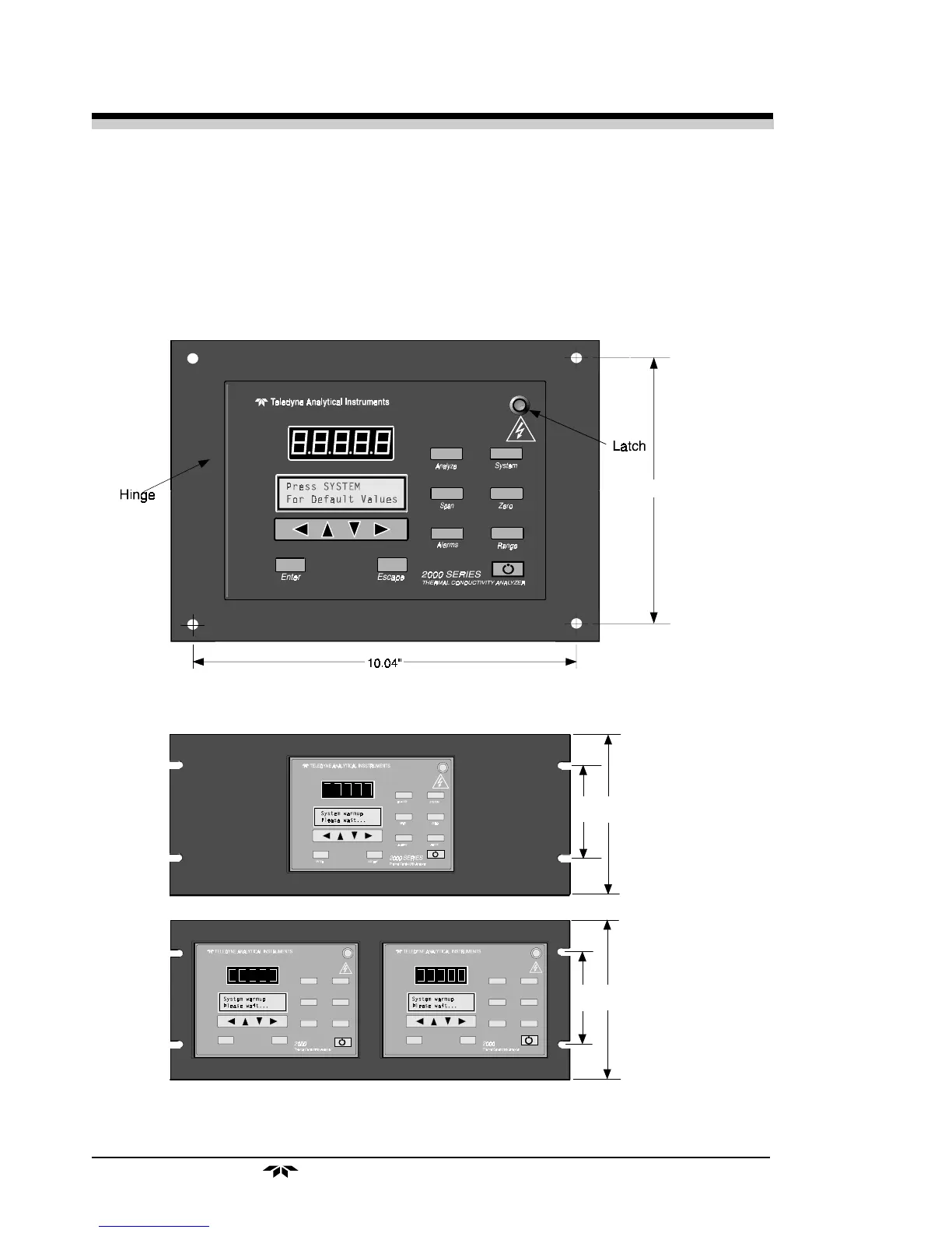
are four mounting holes—one in each corner of the rigid frame. Figure
3-1a contains the hole pattern dimensions. See the outline drawing, at the
back of this manual for overall dimensions.
On special order, a 19" rack-mounting panel can be provided. For
rack mounting, one or two 2000A series analyzers are flush-panel mounted
on the rack panel. See Figure 3-1b for dimensions of the mounting panel.
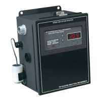
Figure 3-1a: Front Panel of the Model 2000A
Figure 3-1b: Single and Dual 19" Rack Mounts
6.7"
5.75
5.75
8.75
8.75
 Loading...