Do you have a question about the Teledyne 402R-EU and is the answer not in the manual?
Explains how the analyzer measures hydrocarbons using flame ionization detection and amplification.
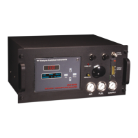
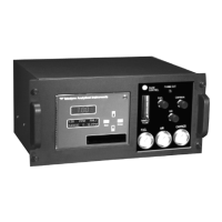
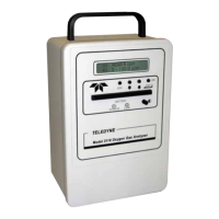
Details the standard series and custom design considerations for the analyzer's build.
Describes the ports for introducing air, fuel, zero, span, and sample gas into the analyzer.
Explains how stable sample flow is achieved via a back-pressure regulation system.
Describes the components and function of fuel and blanket air systems for stable flow.
Details the construction and components of the flame ionization detection cell.
Describes the components of the flame ionization cell, including anode-igniter and thermistor.
Explains the electrometer-amplifier circuit, its function, and handling precautions.
Details the regulated differential power supply providing ±15 VDC for the electrometer-amplifier.
Describes the high voltage anode power supply, its regulation, and output voltage.
Explains the thermistor-controlled circuit that detects flameouts and signals the fuel shut-off.
Describes the components and operation of the flame ignition circuit.
Details the circuit that regulates the isothermal chamber temperature using a thermistor.
Explains the connection of the electrometer-amplifier output to a span potentiometer and digital panel meter.
Details power voltage ranges (115/230VAC), frequency, consumption, and connection.
Identifies gas connection points and diagrams for system setup and operation.
Lists specific fuses used in the instrument and their part numbers for replacement.
Lists supporting gases and hardware required for analyzer operation.
Details essential checks to perform before powering on the analyzer.
Outlines preliminary electronic adjustments needed after installation and checks.
Step-by-step guide to powering on and preparing the analyzer for operation.
Instructions for activating and setting up the supporting gases (Air, Zero Gas, Span Gas, Fuel).
Describes the procedure for igniting the flame and observing indicator lights.
Step-by-step guide to zero and span calibration of the analyzer for accuracy.
Describes the warm-up and stabilization period required after calibration for stable readings.
Outlines requirements for the process gas sample, including condition and pressure.
Covers daily checks and considerations for the day-to-day operation of the analyzer.
Procedure to isolate and check the electronic measurement circuitry for faults.
Procedure for verifying the high voltage anode supply, with warnings about high voltage.
Procedure to check the temperature control circuit for failures affecting analyzer output.
Procedure to diagnose problems with the flame ignition or flame guard circuits.
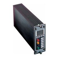
Overview of the analyzer's plug-in printed circuit boards and their interconnections.
Lists technical specifications including ranges, sensitivity, accuracy, and power requirements.
Provides fields for recording application-specific data and recommendations for support gases.
Lists part numbers and descriptions for recommended spare parts for the instrument.
Lists available diagrams and schematics for the analyzer.
| Accuracy | ±1% of Full Scale |
|---|---|
| Response Time | <15 seconds (T90) |
| Range | 0-100% |
| Operating Temperature | 0°C to 50°C |
| Output | 4-20 mA, RS-232 |
| Measurement Range | 0-100% |
| Enclosure Rating | IP66 |
| Sensor Type | Electrochemical |