Installation and Setup cont’d
If you are using a E-MU 0202 USB card, the input gain controls should be set to between 10 and 12 o’clock to obtain this noise floor.
The two pots should be set as close to exactly the same as you can or else initial image rejection will be poor. If your card uses a
software level control, it should be set near maximum with line input selected, and should indicate the noise floor mentioned above.
Some professional sound cards will have fixed inputs.
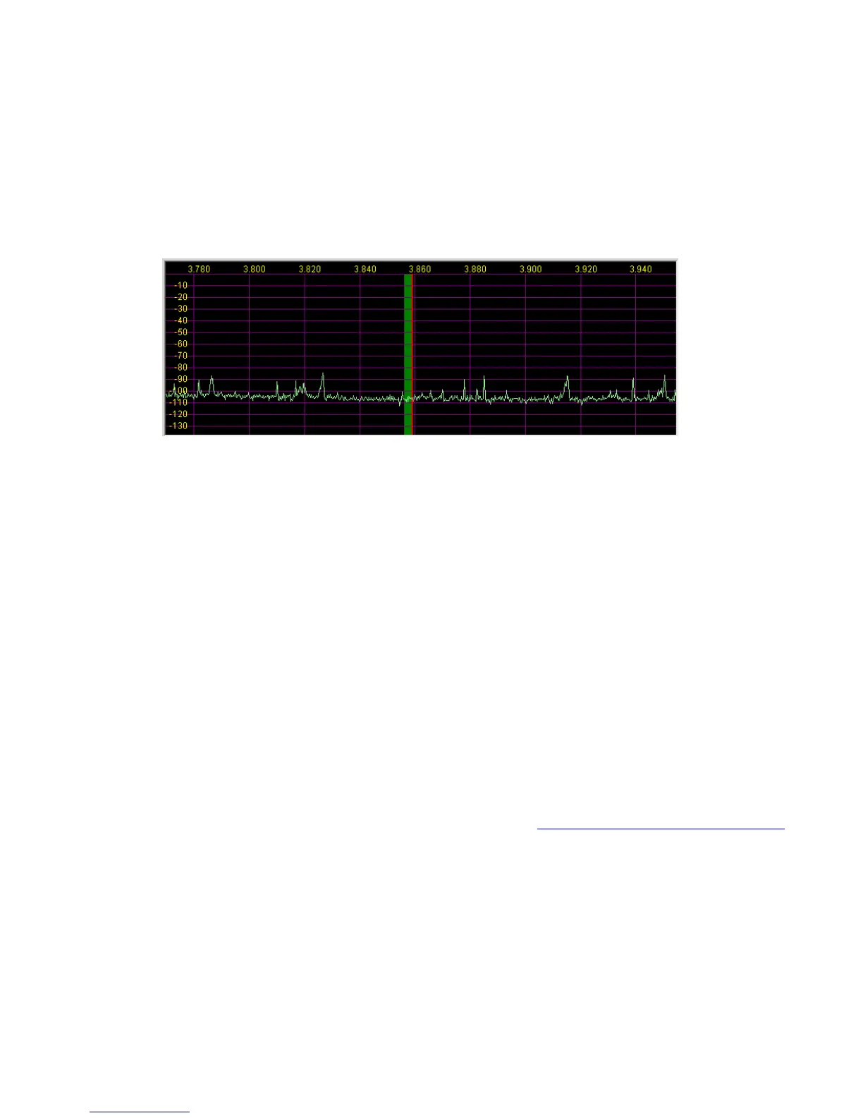
If you are seeing any signals (vertical blips), then there is something in your cabling / ground lift settings that is not right. Small blips,
say 10dB above the noise floor could be the result of radiation from your monitor or USB cabling, and rearranging things might help.
Spurious signals and elevated noise levels can also be due to a noisy switching power supply in your shack. I had tiny blips on an older
PC with a 21" CRT monitor, and had to move the sound card away from the monitor. On my laptop and other PC with LCD monitor I
had no problem. Small blips should not be a problem in practice, especially with AVG off.
Connect an antenna, and the noise floor should jump up a bit, depending on band, and you should see lots of signals if the band is
open, as above. I recommend 40m as a good starting point, since there are always signals, and at night you can see some very strong
ones. If all is OK up to this point, continue to the next section.
Calibration
There are only a few hardware adjustments that need to be made in LP-PAN… filter peaking, overall gain setting and load balance.
Note: Filter peaking is only required for kit versions. All adjustments are made while monitoring the PowerSDR display. Load balance is
done in conjunction with the Image Rejection controls in PowerSDR.
Filter adjustment - To adjust the LP-PAN filter, tune to a strong carrier, S9 or better, and peak C35 for maximum strength. If you don’t
have an insulated tuning tool, a small screwdriver can be used, but you will have to remove the screwdriver between adjustments to
see the effect of the adjustment. After C35 is peaked, adjust C34 for maximum signal.
Gain adjustment - To set the gain display accuracy requires a signal source with known output level. This can come from a calibrated
signal generator, or something as simple as the Elecraft XG1 or XG2 test oscillators, which have an output of about –73dBm
(50uV/S9). Set the K3 preamp and attenuator OFF, and the Preamp setting in PowerSDR to OFF. Turn AVG on in PowerSDR. Connect
your generator to the RX ANT input of the K3, and select RX ANT. Adjust your sound card inputs for a displayed level of –73dBm. If you
run out of range on your sound card input, you can adjust R29 on LP-PAN as well. The pot has about 8dB range. If you have an
adjustable generator, you can check sound card gain for proper dynamic range limits. You can decide the range that is ideal for you,
but as a frame of reference I have mine set to clip at –8 dBm input. In my case, I have the K3 buffer mod installed in my K3. This adds
about 10dB gain ahead of LP-PAN. If you don’t have the mod installed, the clip point and noise floor will be about 10dB higher. Details
of the buffer mod can be found in the Files section of the LP-PAN Yahoo Group site at http://groups.yahoo.com/group/LP-PAN/files.
 Loading...