Installation and Setup cont’d
Image Rejection Adjustment - At this point, strong signals will display an image on the opposite sideband, with 2
nd
harmonics at about
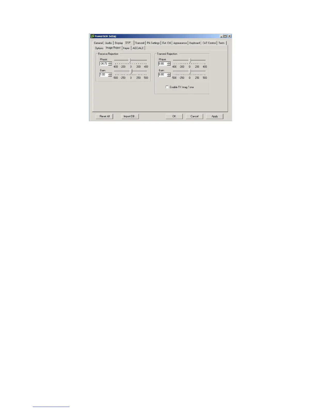
70dB down until clipping is imminent. Image rejection is adjusted in the DSP tab in PowerSDR Setup, under the “Image Reject” sub tab,
shown above. If your sound card has hardware input pots, make sure they are set for the same level. If your sound card has software
level controls, set both channels for the same level. Most software mixers have a way of adjusting the levels together. Also, if there is a
balance control, make sure it is centered, or if there are pan controls, make sure the left channel is panned all the way left and the right
panned all the way right. You can set a quick image null by placing the signal midway between the left edge of the display and the
center. The image will appear midway between the center and right edge. AVG should be OFF for these adjustments. Adjust the phase
and gain sliders for minimum amplitude of the image. The sliders provide a rough adjustment. You must use the Up/Dn arrows to fine
tune the null. The adjustment is quite critical to get maximum null depth. The correct setting should be within approx. +/-100.00 for
Phase, and +/- 50.00 for gain. NOTE: If you have an E-MU 0202 sound card, you might want to try this procedure: Set Gain and Phase
sliders for 0.00, set E-MU left channel pot at 11 0’clock, adjust right channel pot for a rough image null. Then use the sliders/arrows to
fine tune. The extra step may be needed in case the physical pot positions on the E-MU are a little out of alignment. Any future
adjustment in the left pot setting will require a readjustment of the right pot and readjustment of the sliders/arrows.
This will not be the best setting for overall broadband image rejection, however. There is an iterative process for improving the
broadband image rejection, which essentially finds a median setting which will be close for all frequencies, but not perfect at any one
frequency.
The procedure is outlined below.
1) Tune in a strong signal (-50dBm or higher) from a signal generator or nearby transmitter.
2) Tune the K3 to put the image midway between the center of the display and the left end of the display.
3) Set the Image Reject Phase and Gain adjustments for minimum image response. Log the values.
4) Retune the K3 to put the image signal midway between the center and the right end of the display. Adjust for minimum response
and log the values.
5) Set the Image Reject controls for the midpoint of the logged settings.
6) Adjust the Match control on the rear panel of LP-PAN for minimum response
7) Retune the image to the original center/left point. Readjust the gain setting in PowerSDR for minimum image. Log the value.
8) Retune the image to the center/right point and readjust the gain setting for minimum image. Log the value.
9) Adjust the gain setting for midway between the two values if they are not the same.
10) If the gain settings logged in steps 7 & 8 are not very close (within 2.0), then you can repeat steps 6-9 to get closer.
When finished, image rejection should remain at 60dB or more over most of the range as you tune, with maybe a bit lower at the edges
and very near the center, depending on sound card. Results will be better with 96 kHz cards because of the smaller bandwidth. Scott
also plans to add auto image nulling in PowerSDR along the lines of what is done in the Rocky program. This would provide an image
rejection of close to 100dB with no adjustments.
You should now be ready to attach the enclosure top, and continue with the remaining software adjustments.
Global Offset adjustment – LP-Bridge provides an offset value to PowerSDR which keeps the IF center frequency of PowerSDR
synchronized with the K3. Due to slight differences in the reference oscillator in the K3 and the local oscillator of LP-PAN, you must
make a small adjustment to bring the two into exact zero beat. The error will generally be within +/-100 Hz of nominal to start with.
Starting with serial # 208, the nominal offset will be 6000, which includes an intentional 6 kHz offset. This was done to move the center
of the passband slightly to avoid problems with some older or cheaper sound cards which have difficulty near an audio frequency of 0
Hz. On earlier models without the additional offset, the nominal value will be 0.
 Loading...