INSTRUMENT MANUAL
VACUUM GAUGE MODEL MM200
160Phone:(215) 947-2500 fax:(215) 947-7464 e-mail:sales@televac.com web site:www.televac.com
MM-200_im REV M
Page 28 of 160
1. Remove the sensor interface module from its packaging. Examine it for shipping damage. If damaged,
refer to Section 201.
2. Place jumpers in the desired position to select station numbers, setpoint station assignment, etc. as
described in Section 902.
3. Remove the two screws holding the blank cover plate over the module position you plan to use.
4. Align the module with the slots in the instrument and push into place. Press to secure edge connector into
the connector on the motherboard.
5. Reinstall the two screws.
308 DESCRIPTION OF MODULES
Various types of modules are available for installation in
the MM200 gauge. Descriptions of available modules follow as they appear from the rear panel. For detailed
descriptions of available modules and their setup, see Section 902.
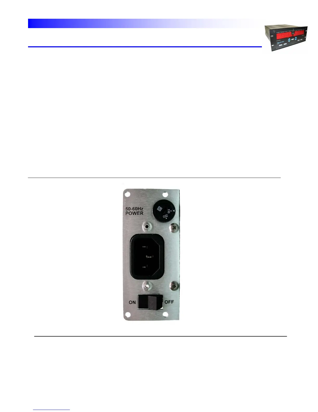
POWER SUPPLY MODULE - The power supply module is located in module slot "0" on the left rear of the
instrument. It contains a plug socket for the power cord, a voltage selection switch and an on/off switch. (Fig. 3.4).
Fig. 3.4 - Power Supply Module