LE910Cx-WE866Cx LTE Bundling User Guide
1VV0301578 Rev. 9 Page 17 of 56 2020-05-26
• Programmable FPGA.
• RF SMA connectors.
• Board to Board connectors for interfacing to EVB main board
• Module specific circuitry which is not part of the generic circuitry of the EVB
Power supply and control interface for the cellular module is provided from the EVB via the
B2B connectors.
To monitor the temperature, a thermistor is placed on the top GND plane, close to the
module which should be representative for the module’s backside temperature.
A programmable FPGA which is included in the MTB provides options for connecting very
functional modem pin to the relevant peripheral M.2 cards hence enabling the most flexible
way to demo interoperability between the LE910Cx module and peripheral accessories.
A typical example of this capability is in the case where 3x M.2 cards (WIFI module, GNSS
module and BT module) are plugged into the M.2 slots while the FPGA is programmed to
perform the correct signals mapping between the LE910Cx and the interfaces of each of
the M.2 accessories.
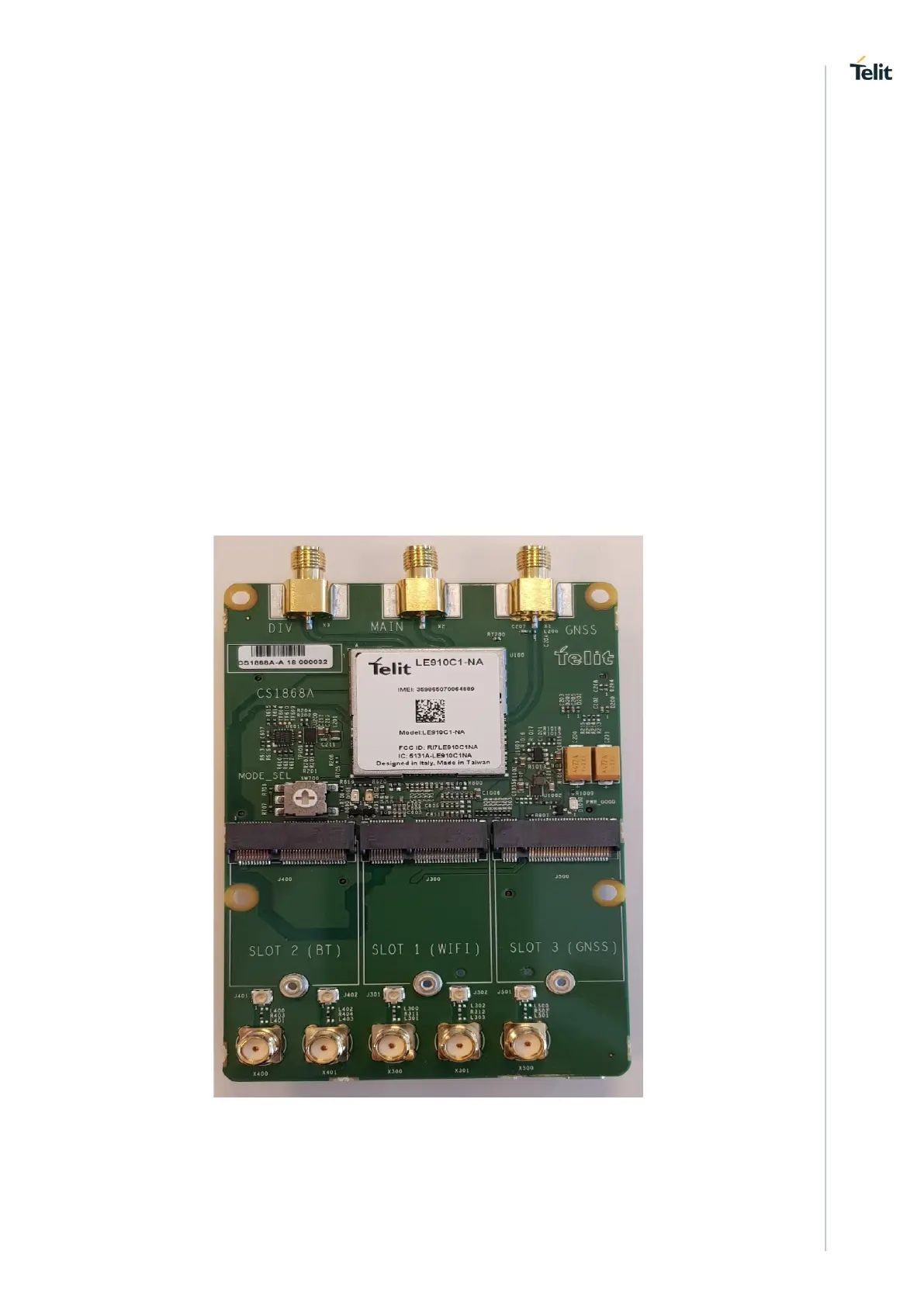
The following images show the MultiTech Interface Board top and bottom views:
Figure 4-2 MultiTech Interface Board - Top View