Do you have a question about the Teltonika FMC150 and is the answer not in the manual?
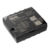
Details the pinout for the FMC150-QJIB0 model's 2x6 socket connection.
Details the pinout for the FMC150-QKIB0 model's 2x6 socket connection.
Step-by-step guide for installing necessary USB drivers on Windows for device connection.
Details on initial device configuration using the Teltonika Configurator software on Windows.
Guidance on properly connecting device wires, emphasizing safety and isolation.
Recommendations for connecting the device's power source, including fuse and voltage checks.
Instructions for correctly identifying and connecting the ignition wire for device operation.
Guidance on properly connecting the ground wire to a suitable point on the vehicle.
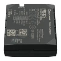
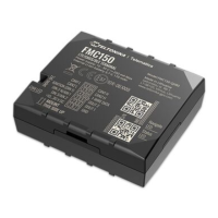
The Teltonika FMC150 is a sophisticated 4G Cat 1 GNSS/GSM/Bluetooth tracker, designed for vehicle monitoring and data acquisition. It features an integrated CAN adapter, internal GNSS/GSM antennas, and an internal battery, making it a compact and versatile solution for various telematics applications.
The primary function of the FMC150 is to track vehicle location using its Global Navigation Satellite System (GNSS) capabilities and transmit this data via its Global System for Mobile Communications (GSM) module. The integrated CAN adapter allows the device to read data directly from the vehicle's Controller Area Network (CAN) bus, providing access to a wealth of information such as speed, fuel level, engine RPM, and other diagnostic parameters. Bluetooth connectivity further enhances its functionality, enabling communication with other Bluetooth-enabled devices and facilitating configuration.
The device is equipped with an internal battery, providing backup power and ensuring continuous operation even if the main vehicle power supply is interrupted. Movement and ignition detection are key features, with the device capable of identifying vehicle movement via an accelerometer and ignition status based on vehicle power voltage. This allows for intelligent data recording, where records are made based on specific events such as a certain time interval passing, a change in vehicle heading, or a significant speed difference.
Configuration of the FMC150 is flexible, supporting both local PC connection and remote SMS commands. The Teltonika Configurator software, compatible with Microsoft Windows operating systems, provides a comprehensive interface for managing device settings, including GPRS parameters for server communication and data acquisition parameters. This allows users to tailor the device's behavior to their specific needs, optimizing track quality and data usage.
The FMC150 also supports firmware updates and CAN configuration uploads over the air (FOTA WEB), simplifying maintenance and ensuring the device always runs with the latest features and vehicle compatibility. Data records can be read from the device, and the configuration can be reset to default settings if needed.
To begin using the FMC150, a Micro-SIM card must be inserted. This process requires gently removing the device cover with a plastic pry tool, ensuring the Micro-SIM card's cut-off corner points forward into the slot. It is crucial that the device is powered off—both external voltage and internal battery disconnected—during SIM card insertion or removal to prevent damage.
The internal battery needs to be placed and connected to the PCB after disassembling the device. It should be secured to the bottom part of the device case using double-sided tape, approximately 15 millimeters from the bottom wall.
Connecting the FMC150 to a PC for configuration can be done via a Micro-USB cable or Bluetooth. For USB connection, appropriate COM port drivers must be installed. The Teltonika Configurator software is then used to load, save, and modify device settings. Bluetooth connection is enabled by default; users can pair with the device using a default password.
Quick SMS configuration offers a convenient way to set up essential GPRS and server parameters without a PC connection. By sending a specific SMS command with APN, username, password, domain, port, and data sending protocol details, the device can be quickly configured to communicate with a server. After successful SMS configuration, the FMC150 will synchronize time and update records to the configured server.
For CAN configuration, the device leverages FOTA WEB, allowing users to upload vehicle-specific CAN configurations remotely. This involves selecting the device in the FOTA WEB interface, creating an "Upload CAN configuration" task, and specifying the vehicle make and model. The upload task will commence during the next scheduled connection to FOTA WEB or can be initiated instantly via an SMS command.
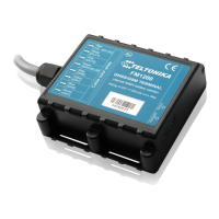
Proper installation and connection are paramount for the FMC150's reliable operation. When connecting wires, it is essential that the module is not plugged in. Wires should be fastened securely to stable, non-moving parts of the vehicle, away from heat-emitting or moving objects. Any exposed wires, especially if factory insulation has been removed, must be re-insulated. If wires are routed externally or in areas prone to damage, heat, humidity, or dirt, additional insulation is recommended. It is critical not to connect wires to the vehicle's board computers or control units.
Connecting the power source requires careful attention. The FMC150 operates on a SELV limited power source with a nominal voltage of +12 V DC, supporting a range of +10 V to +30 V DC. It is advised to connect the power and ground wires directly to the battery terminals, as these are very low impedance points in the vehicle's electrical network. Alternatively, connection to the main power cable inside the fuse box is acceptable. A 3 A, 125 V external fuse should be used. It is important to verify that power remains available even when the car computer goes to sleep mode.
The ignition wire should be connected to a real ignition source that provides continuous power when the ignition is on, not an ACC (accessory) wire. The ground wire must be connected to the vehicle frame or metal parts fixed to the frame, ensuring good contact by scrubbing paint from the connection spot if necessary. Connecting the ground at an arbitrary point on the car's mass is unacceptable, as it can lead to unstable operation and device failure.
Safety information emphasizes that the device should not be disassembled. If damaged, especially with exposed or compromised power supply cables, the device should not be touched before unplugging the power supply. The FMC150 is designed for mounting in a limited access zone, inaccessible to the operator. All related devices must comply with EN 60950-1 standards. It is not designed as a navigational device for boats.
Precautions also highlight that wireless data transferring devices can cause interference with nearby electronics. The device should only be connected by qualified personnel and firmly fastened in its designated location. Programming should be performed using a PC with an autonomous power supply. The device is susceptible to water and humidity, and installation or handling during a lightning storm is prohibited.
| Digital Outputs | 2 |
|---|---|
| GSM | Quad-band 850 / 900 / 1800 / 1900 MHz |
| 2G bands | 850 / 900 / 1800 / 1900 MHz |
| SMS | Yes |
| Power Supply | 10 - 30 V DC |
| GNSS | GPS, GLONASS |
| 1-Wire | 1-Wire data protocol |
| GNSS Support | GPS, GLONASS |
| Antenna Type | Internal |
| Protocols | TCP, UDP |