Do you have a question about the Teltonika FMC650 and is the answer not in the manual?
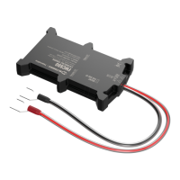
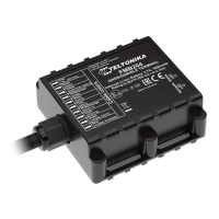
Guidelines for securely fastening and isolating device wires to prevent damage and interference.
Instructions for connecting the device to the vehicle's power supply, ensuring continuous availability and safety.
Steps to correctly identify and connect the ignition wire for proper device operation and status monitoring.
Best practices for establishing a reliable ground connection to the vehicle's frame or metal parts for stable operation.
Specifies the minimum, typical, and maximum supply voltage requirements for the device's operation.
Details the drain current and static resistance characteristics for the device's digital output ports.
Outlines the input resistance values for the device's digital input pins (DIN1, DIN2, DIN3).
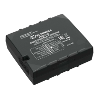
| Weight | 120 g |
|---|---|
| GNSS | GPS, GLONASS, GALILEO, BeiDou |
| Tracking sensitivity | -167 dBm |
| Hot start | 1 s |
| 2G bands | 850/900/1800/1900 MHz |
| SMS | Yes |
| Bluetooth | Yes |
| Bluetooth peripherals supported | Yes |
| Internal Back-up battery | Yes |
| Digital Outputs | 2 |
| Analog Inputs | 2 |
| CAN adapters | Yes |
| 1-Wire | Yes |
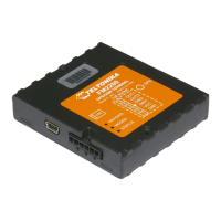
| RS232 | Yes |
| USB | Yes |
| LED indication | Yes |
| Ingress Protection Rating | IP54 |
| Sleep modes | Yes |
| SMS configuration | Yes |
| GPRS commands | Yes |
| Fuel monitoring | Yes |
| Ignition detection | Yes |
| GNSS Update Rate | 10 Hz |
| GNSS Channels | 72 |
| GPS Accuracy | 2.5 m |
| Warm start | < 25 s |
| Technology | GSM / GPRS |
| Connectivity | Quad-band GSM: 850 / 900 / 1800 / 1900 MHz |
| Data transfer | GPRS |
| Power supply range | 9 - 30 V DC |
| Communication Interfaces | RS232, USB, Bluetooth |
| GNSS antenna | External |
| GSM antenna | External |
| Operating environment | Automotive |
| Operating Temperature | -40 °C to +85 °C (without battery) |
| Storage Temperature | -40 °C to +85 °C |
| Humidity | 5% to 95% non-condensing |
| Scenarios | Fleet management |
| Configuration and firmware update | FOTA |
| Time Synchronization | NTP |
| Wireless Connectivity | Bluetooth |
| Certifications | CE |