Display
Name&Description
Range
Display
condition
Default
value
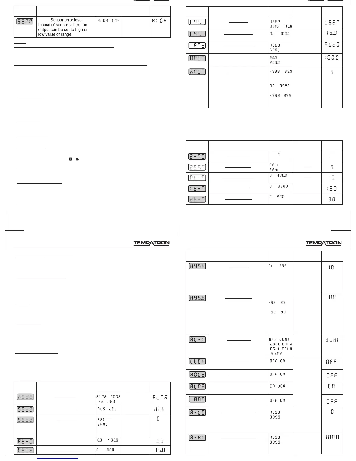
Anti-resetwindup
Anti-resetwindup%
ManualReset
/
to
%
to
(for0.1
resolution)
to
(for1 )
to
(foranalog
input)
o
o
ARW=MAnL
Proportional
band>0and
Integraltime
=0.
20
Programming.
Cycletime
Cycletime-user
/
/
to
sec
Cycletime=
USEr
Display
Name&Description
Range
Display
condition
Default
value
Zonenumber
to
ZonePID=
YES(inlevel4)
Zonesetpoint
to
Proportionalband
Integraltime
Derivativetime
to
sec.
to
sec.
to
o
Pb-n>0
Pb-n>0
*NOTE: ForProportionalband,IntegraltimeandDerivativetimen=1to4
*
*
*
IfSetMode=ZoneandZonePID=YES,thefollowingparameterswill
beprompted.
IfSetMode=AllandZonePID=YES,Theparametersexceptthe
shadedones(i.e.Pb-1,It-1,dt-1)willbeprompted.
PIDcontrol
PIDcontrol
Display
Name&Description
Range
Display
condition
Default
value
/
NOTE:
HC mode
SET 2 MODE:
SET 2 TYPE:
ALARM MODES:
ALARM LATCH:
HOLD ALARM:
ALARM ANNUNCIATOR:
SENSOR ERROR LEVEL:
In only the following parameter will be prompted :-
In case of analog retransmission only the following parameters will be prompted:
1. Set 2 value - this parameter will be prompted as db (dead band)
2. Proportional band - cool (Pb-C)
3. Cycle time - cool (cyc.t)
1. A-LO : Analog low scaling.
2. A-HI : Analog high scaling.
3. S.ERR : Sensor error level.
Display is with fixed 1 resolution for TC/RTD and as per decimal point selected for analog
input.
AlrM: Set2 can be programmed as alarm.
NonE: If set2 is not required it can be programmed as none.
Fd: Set2 programmed in cooling mode.(output ON when above the setpoint).
rE: Set2 programmed in heating mode.(output ON when below the setpoint)
AbS: Absolute alarm is a self-existent alarm independent of the main set point.
DEV: The alarm is activated at an error on the main set point.
(Refer for detailed explanation).
When Latch is ON, the alarm once activated remains activated even when the error is
removed. To deactivate the alarm, it has to be acknowledged by selecting AL-NO from the
front online options and pressing + .
When HOLD is ON, in any alarm mode, it prevents an alarm signal on power-up. The alarm is
enabled only if the process temperature is within the alarm range.
When alarm annunciator is ON, during alarm condition, visual annunciation is given by the
upper display altering between AL-NO and process temperature where NO is the alarm
number. The annunciator may be disabled by selecting function ANN as OFF.
This parameter determines the analog retransmission output level in case of sensor failure.
For eg : In case of 4-20mA retransmission output, if the sensor error level is set to High, 20mA
will be available at the output at all times incase of input sensor failure.
O
PARAMETER EXPLANATIONS :
•
•
•
•
•
•
•
USER GUIDE
23
Programming.
ForAnalog
outputif
Mainoutput
=Relay2
Display
Name&Description
Range
Display
condition
Default
value
Hysteresis
to
O
C
1.Set2
mode=Fd/rEV/
ALrM(not
sensorbreak);
2.Heatcool
mode(
Pb-C=0)
Hysteresisbias
Alarm1mode
Alarmlatch
TC/RTD:
C
Analoginput:
to
asper
decimal
point
selected.
to
O
/
/ /
/ /
/
/
1.Set2
mode=Fd/rEV
/ALrM(not
sensorbreak);
2.Heat-cool
mode
(Pb-C=0)
Set2
mode=ALrM
These
parameters
arenot
promptedif
Alarm1mode
isOFF.
HoldAlarm
/
RelaystatusforAlarm1
AlarmAnnunciator
/
/
Analoglowscaling
Analoghighscaling
to
to ForAnalog
outputif
Mainoutput
=Relay2
22
Programming.
For Analog
retransmission
if Main output
= Relay2 in
Level 4
Display
Name&Description
Range
Display
condition
Default
value
Set2Mode *
Set2Type
/
/ /
/
NotforHeat-
coolmode.
Set2mode=
Fd/rEV.
5. -AUXILIARY OUTPUTMODESLEVEL 2
PARAMETER EXPLANATIONS :
!
!
!
!
!
AUTO TUNING:
OUTPUT POWER LIMITS:
TIMER:
CYCLE TIME:
ANTIRESET WINDUP:
Auto tuning is a function whereby the controller learns the process characteristics by itself
and automatically sets the required P,I and D values. The new P,I,D parameters will be
stored in non-volatile memory automatically. TUNE ON is indicated by ‘T’ LED blinking.
(For detailed explanations of PID parameters refer USER GUIDE).
These parameters are used to limit the minimum and maximum controller output power.
The output power lower limit will ensure that a minimum percentage of output (as per
requirement) is available in case any process disturbances or setpoint changes occur.
The output power high limit ensures that in case any process disturbance or set point
changes occur, the maximum value of output is limited to a value as per requirement.
TIMER is main output restart time. In this main output once turned OFF will turn ON only
after set time even if the temperature has increased and is more than the set temperature.
This is needed to prevent the compressor from restarting in a short time (less than the set
time).
There are 3 selectable modes for programming cycle time:
USEr: User can program the cycle time. The mode will be altered to AutO when put to
autotune.
Usr.F: User can fix the cycle time. This has the highest priority.
AutO: This is recommended. The cycle time value is calculated automatically during
autotune.
The anti-reset windup (ARW) inhibits the integral action until the PV is within the
proportional band thus reducing overshoot on start-up. If the selection is -
1. AutO: The value will be calculated automatically during autotune (Recommended).
2. ManL: The value can be fed manually by the user.
Set2Value
Proportionalband-Cool
to
to
Notprompted
ifSet2mode=
alarm&alarm
mode=S.Brk.
Heat-cool mode
Cycletime-Cool
to sec Pb-C>0
21
Programming.
NOTE: *-Ifset2mode=none,nootherparameterswillbeprompted.
 Loading...