WIRINGINSTRUCTIONS
CAUTION:
1.Topreventtheriskofelectricshockpowersupplytotheequipmentmustbe
keptOFFwhiledoingthewiringarrangement.
2.Terminalsandelectricallychargedpartsmustnotbetouchedwhenthepower
isON.
3.Wiringshallbedonestrictlyaccordingtotheterminallayoutwithshortest
connections.Confirmthatallconnectionsarecorrect.
4.UseluggedterminalstomeetM3.5screws.
5.Toeliminateelectromagneticinterferenceuseofshortwirewithadequate
ratingsandtwistsofthesameinequalsizeshallbemade.
6.Cableusedforconnectiontopowersource,musthaveacrosssectionof1or
greater.Thesewiresshallhaveinsulationcapacitymadeofatleast1.5KV.
INSTALLATIONGUIDELINES
MechanicalInstallation:
Forinstallingthecontroller
1.Preparethepanelcutoutwithproperdimensionsasshown.
2.Removetheclampfromthecontroller.
3.Pushthecontrollerintothepanelcutout.Securethecontrollerinits
placebypushingtheclampfromtherearside.
CAUTION:
The equipment in its installed state must not come in close proximity to any
heating sources, caustic vapors, oils, steam, or other unwanted process by-
products.
!
8
Installation
ELECTRICAL PRECAUTIONSDURINGUSE
Electricalnoisegeneratedbyswitchingofinductiveloadscancreatemomentary
disruption,erraticdisplay,latchup,datalossorpermanentdamagetotheinstrument.
Toreducenoise:
A)UseofMOVacrosssupplyoftemperaturecontroller&snubbercircuits
acrossloadsarerecommended.Partnumbersareasfollows:
1.Snubber:APRC-01.
B)Useseparateshieldedwiresforinputs.
C)Theunitshouldpreferablybeshieldedfromthecontactor.
EMC Guidelines:
1.Use proper input power cables with shortest connections and twisted type.
2.Layout of connecting cables shall be away from any internal EMI source.
OVERALL DIMENSIONS (Alldimensionsinmm)
E
A
PanelCutout
F
D
B
C
G
A
B C D E F G
PID500
48 48 100 45 7 45 45
96 96
74.5
90
10
92 92
PID330
96 48
74.5
90 10 92 45
PID110
MODEL
S
DIM
! DERIVATIVE APPROACH CONTROL:
AUTO-TUNE OF HEAT/COOL SYSTEMS:
ANALOG OUTPUT-RETRANSMISSION:
Derivative approach control (DAC) helps in reducing overshoot at startup. The control
output cutoff point is derived as DAC x Proportional band. Note that the DAC value is
automatically calculated and fed after autotuning (if tuning is initiated at startup).
During Autotune of heat/cool systems, the controller switches the cooling output (O2) ON
and OFF in addition to the heat output (O1). The heat/cool overlap deadband parameter
(db in Level 2) determines the amount of overlap or deadband between the two outputs
during Autotune.
For most applications, set this parameter to 0.0 prior to starting Autotune. After the
completion of Autotune, this parameter may need to be reset. It is important that external
load disturbances be minimized, and if present, other zone controllers idled as these may
have an effect on the PID constant determination.
Some water cooled processes exhibit an extreme non-linear gain characteristic. That is,
the process cooling gain starts very high and flattens out deeper into the cooling region.
This effect may result in regular oscillations at setpoint as the controller applies heat to
counteract the effect. These processes may benefit from a lower cooling fan setting and/or
reduced water flow in the jacket or manifold. The process heat and cool gains should be
balanced as much as possible, and the controller gains adjusted to the process.
1. The analog retransmission output feature allows the retransmission of the control
output to an external device.
2. The output is scaled by use of Analog low and high scaling points in level 2 of the
programming menu. The analog output will be proportional to PV (derived from
Analog Low and High scaling.)
3. A-LO : Displays the value that corresponds to 0V, 0/4mA as selected.
A-HI : Displays the value that corresponds to 10V or 20mAas selected.
4. Note that the main output selection in level 4 has to be relay 2.
!
!
UserGuide
35
!
!
!
“antireset wind-up”
PROPORTIONAL BAND:
MANUAL RESET:
INTEGRAL TIME:
DERIVATIVE TIME
Proportional band is the area around the set point where the controller is actually
controlling the process; the output is at some level other than 100% or 0%.
Proportional band is expressed in terms of degree centigrade.
If the proportional band is too narrow an oscillation around the setpoint will result. If the
proportional band is too wide the control will respond in a sluggish manner, could take a
long time to settle at set point and may not respond adequately to upsets.
Virtually no process requires precisely 50% output on single output controls or 0% output
on two output controls. The adjustment called manual reset allows the user to redefine the
output requirement at the setpoint. A proportioning control without manual or automatic
reset will settle out somewhere within the proportioning band but likely not on the setpoint.
Integral time is defined as the time, in seconds, which corrects for any offset (between
setpoint and process variable) automatically over time by shifting the proportioning band.
Integral action (also known as “automatic reset”) changes the output power to bring the
process to setpoint. Integral times that are too fast (small times) do not allow the process
to respond to the new output value. This causes over-compensation and leads to an
unstable process with excessive overshoot. Integral times that are too slow (large times)
cause a slow response to steady state errors. Integral action may be disabled by setting
the time to zero. If time is set to zero, the previous integral output power value is
maintained. If integral action is disabled, manual reset is available by modifying the output
power offset (“MNL.r” initially set to zero) to eliminate steady state errors. The controller
has the feature to prevent integral action when operating outside the proportional band.
This feature is called .
Derivative action is used to shorten the process response time and helps to stabilize the
process by providing an output based on the rate of change of the process. In effect,
derivative action anticipates where the process is headed and changes the output before
it actually “arrives”. The derivative time is calculated in seconds. Increasing the derivative
time helps to stabilize the response, but too much derivative time coupled with noisy
signal processes, may cause the output to fluctuate too greatly, yielding poor control.
None or too little derivative action usually results in decreased stability with higher
overshoots. No derivative action usually requires a wider proportional and slower integral
times to maintain the same degree of stability as with derivative action. Derivative action is
disabled by setting the time to zero.
!
34
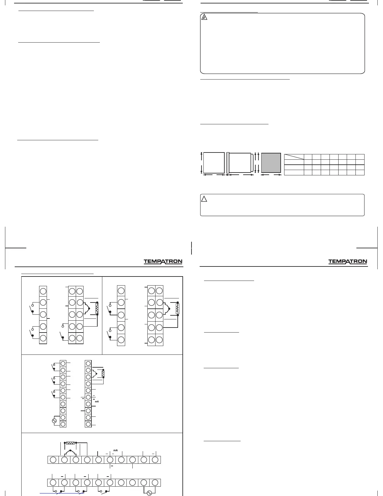
2. TERMINAL CONNECTIONS
9
Installation
PID500
+
SSR1/
ANA OP
COM1
COM2
COM3
NO1
NO2
NO3
+
+
+
+
-
-
-
-
SSR2
SSR3
N
L
-
11
12
13
14
15
16
17
18
19
20
RS485
RTD3
mV
TC/RTD1
+
+
mV
TC/RTD2
-
-
1
2
3
4
5
6
7
8
9
10
+
V
+
+
MI/
CT/
R-SP
PID110
PID330
1
6
8
9 10
5
4
3
2
16 17 18
19 20
15
14
13
1211
7
+
SSR1/
ANA OP
COM1 COM2 COM3NO1 NO2 NO3
+
+
+
+
+
+
SSR2 SSR3
LN
RS485
V
RTD3
mV
TC/RTD1
+
+
mV
TC/RTD2
-
-
-
MI/CT/R-SP
+
RTD3
ANA IP
TC/RTD1
+
+
+
-
ANA IP
TC/RTD2
-
-
RS485
12
7
13 8
14
9
15 10
COM2
SSR1/0-5V/
0-10V/4-20mA
SSR2
NO1
COM1
NO2
2
1
3
4
5
+
-
+
-
L (+)
6
11
(-)N
COM3
NO3
+
-
SSR3
NOTE: Terminals11to15areoptional
NOTE: Validforoptionalconfiguration.
RTD3
ANA IP
TC/RTD1
+
+
ANA IP
TC/RTD2
-
-
7
13 8
14
9
15 10
COM2
SSR1/0-5V/
0-10V/4-20mA
SSR2
NO1
COM1
NO2
2
1
3
4
5
+
-
+
-
L (+)
6
12
11
(-)N
+
-
+
-
RS485
CT/MI/R-SP
UserGuide
 Loading...