CONTENTS
Pageno.
1. Features............................................................... 1
2. Orderinginformation............................................ 2
1. SafetyInformation................................................ 7
2. Terminalconnections........................................... 9
3. Sensorinputwiring.............................................. 10
4. Controloutputwiring............................................ 10
1. Functionmenu..................................................... 13
2. Keys' description.................................................. 15
3. Level0-Inputparameters..................................... 16
4. Level1-Outputparameters.................................. 18
5. Level2-Auxiliaryoutputmodes............................ 21
6. Level3-Alarm2module....................................... 24
7. Level4-Specialfunctions..................................... 25
8. Level5-Communicationparameters....................28
9. Level6-Lockoutmodule....................................... 29
............................................................... 33
..........................38
A)OVERVIEW.
C)INSTALLATION.
D)
E)USERGUIDE
F)CONFIGURATIONRECORDSHEET
B)SPECIFICATIONS
PROGRAMMING.
....................................................... 3
Notes
Notes
43
42
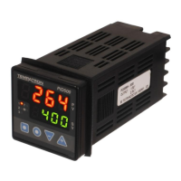
SALIENTFEATURES
? UniversalInput
17 typesincludingsignalinputs.userselectable
? Selectablelowerdisplay
Userselectablelowerdisplayoptionsenablequicksettingofdifferent
parameterssuchasSetpoints,Alarms,PIDvalues,Tuningetc.
? ZonePID
4programmablecontrolzones.
? Outputs
Insignaloutputmodelsoutputisselectableascontroloutputor
retransmissionoutput.
? SpecialModes
Userselectablespecialmodes
-Heat-CoolPID
-Auto/Manual
-Singlepointramp/soak.
-Softstart.
4 Sensorbreakindication
4 Sensorerrorcompensation
4 Programmableparameterlockouts
4 85to270VAC/DCsupply
4 Compliance-
4 IP66frontpanelprotection
Overview
1
Optional Features
4
4
4
4
4
4
4
4
Extra Alarm output
Heater current monitoring
Linear DC outputs (Factory set)
(0 to 10V, 0 to 5V, 0/4 to 20mA)
Remote set-point input
Motorised input
RS-485 MODBUS communication
12 VDC output to drive SSR.
24 VAC/DC supply voltage models
48x48
96x48
96x96