6
Sensortype
Range
Sensortype
Range
J
-200to750 C
o
E
K
-200to1350 C
o
B
T
-200to400 C
o
N
R
0to1750 C
o
L
S
0to1750 C
o
U
C
0to2300 C
o
W
PlatinelII
0to1390 C
o
PT100
-200to750 C
o
+149to1820 C
o
-200to1300 C
o
-200to C600
o
-200to C900
o
0to2300 C
o
-100to850 C
o
Signalinputs:
Inputtype
LinearmV
Voltage
Current
Range
-5to56mV
0to10VDC
0to20mA
Specifications
CE.
AsperBSEN61010.
AsperBSEN61326.
IP66.
Compliance
LVD
EMC
Panelsealing
8.SAFETY ANDEMCSTANDARDS.
9.WEIGHT:
10.HOUSING:
11.INPUTSENSORRANGES(for1 Cresolution):
PID500:195gms;PID110:250gms;PID330:295gms
Flameretardantengineeringplastic.
o
12.INPUTSELECTIONJUMPERASSIGNMENTS:
NOTE: SensorselectiontobedoneinLevel0ofprogrammingalso.
ShortrespectivepinsofJP3&JP4asper
thetablegivenbelowforhardwareselection
ofinputsensortypes:
JP4
FECD
JP3
XBA
4-20mA
(BA)
(CD)
XBA
FECD
TC/RTD/LIN(mV)
Inputtype
0-10V
JP3
(XB)
(XB)
JP4
(FE)
(EC)
XBA
XBA
FECD
FECD
UserGuide
!
How to tune the Zones
To tune, say, Zone 1 program the following:
Zone PID:
There are 4 control Zones each having a set point and associated P, I and D values which
can be programmed as per the process requirements. A control Zone is selected
automatically and implemented as per the set value programmed, to accommodate
changing process requirements. The corresponding P, I,D values will be used to control
the process. The main advantage of Zone PID is in processes where there is a
requirement of frequent tuning, due to change in setpoint. Consider a case where the
process needs to be controlled at two different set points: 100 C and 400 C.
The Zone set points may be programmed as:
1. Zone setpoint 1 (Level1) : 150 C (This implies that for 0 < set1 < 150, Zone1 PID
values will be considered.)
2. Zone setpoint 2 (Level1) : 450 C (This implies that for 150 < set1 < 450, Zone2 PID
values will be considered.)
The P, I, D values for the respective Zones can be manually fed or can be tuned
automatically.
NOTE : Zone setpoint is not the tuning setpoint.
1. Set1 (Online) = 100 C (for eg.) (Zone 1 : 0 - 150 C)
• Set1 < Zone setpoint 1.
• The PID settings derived after tuning are stored in Zone 1.
• After tuning, for 0 < Set1 < 150 C, PID settings of Zone 1 are applicable.
2. Program Tune = ON (in Level 1 or Online)
3. After tuning the controller is automatically loaded with the new PID values.
Now to tune the next Zone, Zone 2, program the following:
1. Set 1 (Online) = 400 C (Zone 2 :150 - 450 C)
• Zone Setpoint 1 < Set 1 < Zone setpoint 2.
• The PID settings derived after tuning are stored in Zone 2.
• After tuning, for 150 < Set1 < 450 C, PID settings of Zone 2 are applicable.
Similarly, the four different Zones can be programmed.
O O
O
O
O O
O
O O
O
Note:
Note:
37
!
1.
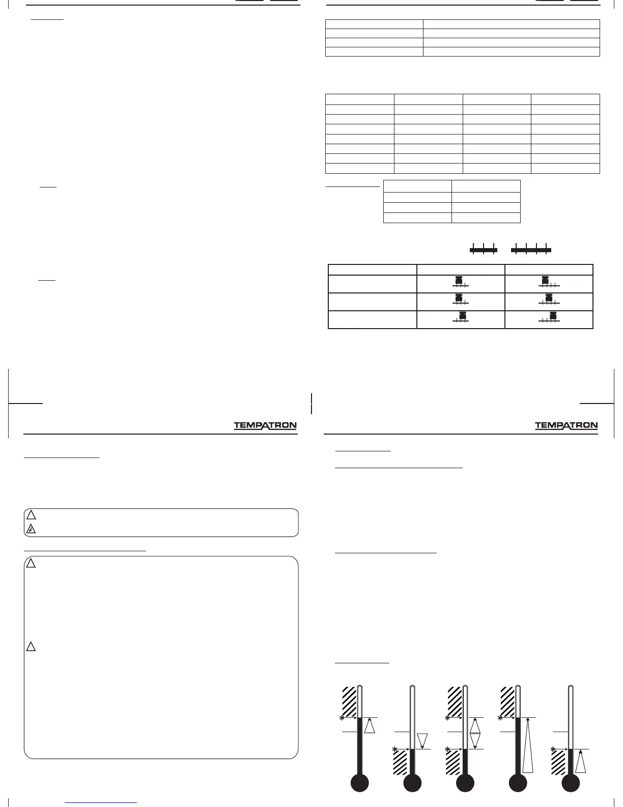
Full scale High Alarm:
Refer Fig: d.
Full scale Low Alarm:
Refer Fig: e.
2.
Deviation High Alarm:
Refer Fig: a.
Deviation Low Alarm:
Refer Fig: b.
Deviation Band Alarm:
Refer Fig: c.
3.
ALARM MODES:
Absolute alarms (Independent Alarm) :
Deviation alarms (Error alarm):
BREAK ALARM:
Absolute alarm is a self-existent alarm independent of the main set point.For eg. If the
main set point is 100 C and absolute alarm is set as 110 C, the alarm will be activated at
110 C.
There are two absolute alarms-
sets off alarm signal when temperature rises above set point to a
pre-set temperature above scale minimum.
sets off alarm signal when temperature falls below setpoint to a
pre-set temperature above scale minimum.
This alarm is activated at an error on the main set point. For eg. If the main set point is
100 C and deviation alarm is set to +5 C then the alarm will be activated at 100+5=105
C. Incase of deviation band alarm the alarm will be activated on both sides of set point i.e.
At 95 and 105.
There are three deviation alarms -
sets off alarm signal when temperature rises above a pre-set
temperature above the set point.
sets off alarm signal when temperature falls below a pre-set
temperature below the set point.
sets off alarm signal when temperature rises above or falls below
a pre-set temperature above or below the set point.
Break Alarm: sets off alarm signal when sensor break / under range occurs.
O O
O
O O
O
UserGuide
Deviationlowalarm Deviationbandalarm Fullscalehighalarm FullscalelowalarmDeviationhighalarm
SP2
SP2
SP2
SP2 SP2
SP2
SP
setpoint
SP
setpoint
SP
setpoint
SP
setpoint
SP
setpoint
Alarm
state
Fig:a.Fig:b.Fig:c.Fig:d.Fig:e.
36
!
SAFETY SUMMARY
This manual is meant for the personnel involved in wiring, installation, operation, and
routine maintenance of the equipment. All safety related codifications; symbols and
instructions that appear in this operating manual or on the equipment must be strictly
followed to ensure the safety of the operating personnel as well as the instrument.
If the equipment is not handled in a manner specified by the manufacturer it might
impair the protection provided by the equipment.
Read complete instructions prior to installation and operation of the unit.
Risk of electric shock.
CAUTION:
CAUTION:
1.SAFETY INFORMATION
INSTALLATIONINSTRUCTIONS
CAUTION:
CAUTION:
1.Thisequipment,beingbuilt-in-type,normallybecomesapartofthemaincontrol
panelandinsuchcasetheterminalsdonotremainaccessibletotheenduser
afterinstallationandinternalwiring.
2.Conductorsmustnotcomeincontactwiththeinternalcircuitryoftheequipment
orelseitmayleadtoasafetyhazardthatmayinturnendangerlifeorcause
electricalshocktotheoperator.
3.Circuitbreakerormainsswitchmustbeinstalledbetweenpowersourceand
supplyterminalstofacilitatepower'ON' or'OFF' function.Howeverthisswitchor
breakermustbeinstalledinaconvenientpositionnormallyaccessibletoan
operator.
1.Theequipmentshallnotbeinstalledinenvironmentalconditionsotherthan those
specifiedinthismanual.
2.FuseProtection-Theequipmentdoesnotcontainbuilt-infuse.Installationof
externalfuseforelectricalcircuitryishighlyrecommended.Recommendedrating
ofsuchfuseshallbe275VAC/1Amp.
3.Sincethisisabuilt-intypeequipment(findsplaceinmaincontrolpanel),its
outputterminalsgetconnectedtohostequipment.Suchequipmentshallalso
complywithbasicEMI/EMCandsafetyrequirementslikeBSEN61326-1and
BSEN61010respectively.
4.Thermaldissipationofequipmentismetthroughventilationholesprovidedon
chassisofequipment.Suchventilationholesshallnotbeobstructedelseitcan
leadtoasafetyhazard.
5.Theoutputterminalsshallbestrictlyloadedtothemanufacturerspecified
values/range.
!
!
7
Installation
MAINTENANCE
1.The equipment should be cleaned regularly to avoid blockage of ventilating parts.
2.Use soft cloth for cleaning. Do not use isopropyl alcohol or any other organic
cleaning agent.
 Loading...