S.P.High limit
S.P. Low limit
Change password
New password
Hand O/P
%age
P.B - main
Integral
time
Derivative
time
Manual
reset
P.B - cool
Change
password
New
password
INPUT
PARAMETERS
OUTPUT
PARAMETERS
(mainoutput)
*ALARM2MODULE
(output3)(optional)
LOCKMODULE
(online
parameters)
LOCKMODULE
(levels)
NOTE:- LEVEL 5
LEVEL 9
LEVEL 10
-CommunicationsModule.
-Heatercurrentmonitorinput.
-Motorisedinput/Remotesetpointinput.
Detaileddescriptionoftheabovelevelswillbeprovidedasanaddendumwiththe
respectivemodels.
SPECIAL
FUNCTIONS
AUXILIARY OUTPUT
MODES (output 2)
Latch alarm
Hold alarm
Alarm status
Annunciator
Analog Low
Scale
Analog High
Scale
Sensor error
level
14
Programming
Integral time
Derivative time
Derivative approach
control
Cycle time
Cycle time (user)
Anti reset windup
ARW percentage
Manual reset
Proportional
band - heat
Timer
Sensor open
selection
Sensor fail
power level
P V bias
Filter time
constant
Rounding
increment
Standby mode
Reset all
Soak time
O/P power
dampening
UserID
Programaccesssettings #
to
/
Display
Name&Description
Range
Display
condition
Default
value
8. -PROGRAMMABLEPARAMETER
LOCKOUTMODULE
LEVEL 6
LockSet1
LockSet2
LockSet3
Locktuneparameter
LockHandparameter
/
/
/
/
/
/
/
/
/
/
Display
Name&Description
Range
Display
condition
Default
value
#IfLOCKselectionisONL,thefollowingparameterswillbeprompted.
Lockproportionalband
Lockintegraltime
Lockderivativetime
LockManualresetparameter
Lockproportionalband-cool
/
/
/
/
/
/
/
/
/
/
Programming
29
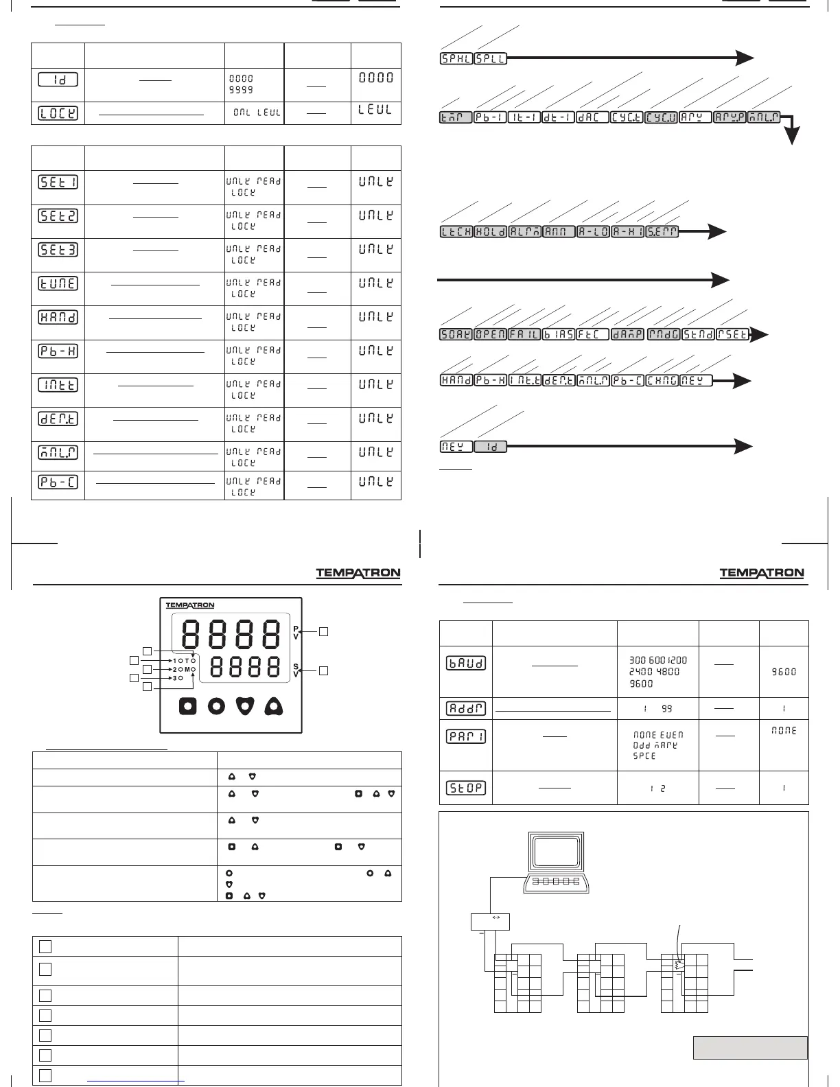
8. -COMMUNICATIONPARAMETERS(OPTIONAL)LEVEL 5
Programming
RS232C485
CONVERTER
1
1 1
6
6 6
7
7 7
8
8 8
9 9 9
10 10 1015 15
14
14 14
13 13 13
12
12 12
11
11 11
3
3 3
4
4 4
5
5 5
2
2 2
+
15
+
+
Terminatingresistor
(100ohm,½watt)
RS485 RS485 RS485
SLAVE1 SLAVE2 SLAVE32
CONNECTIONDIAGRAM
Note:
1.Maximum32slavecontrollerscanbeconnectedtothemaster.
2.Thetotalcablelengthshouldnotexceed500meters.
3.Useshieldedtwisted-paircablesforRS485connections.
4.Useterminatorshavingaresistanceof100ohm(½watt).
28
Master
BaudRate
CommunicationstationNo.
Display
Name&Description
Range
Display
condition
Default
value
Parity
Stopbit
/ /
/
to
/
/
/
RS485-RS232 Converter
Part no.- AC-RS485-RS232-01
5
4
3
6
7
1
2
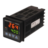
INDICATIONSANDDISPLAY
2
5
6
7
1
Process-value(PV)
Set-value(SV)
3
Relay1(1)
4
Relay2(2)
Relay3(3)
M
T
Displaytheprocesstemperaturevalue.
Displaysthevalueofthelowerdisplayoption
selected.Bydefaultdisplayisset1value.
IndicatesthestatusofMainoutput(relay1).
IndicatesthestatusofAlarmoutput(relay2).
Indicatesthestatusof relay3).Alarmoutput(
IndicationforFixedManualoutput.
IndicationforTuninginprogress.
15
Programming
Keypress
Functions
Toenterorexitprogrammode
Tochangelevels
Toviewfunctiononthesameleveland
todisplaythecurrentoption.
Toincreaseordecreasethevalueofa
particularfunction.
Toviewandchangeparametersonline
+ togetherfor3seconds
or tillLevelisdisplayed. + /
toincreaseordecreasethelevelnumber.
or keyoncetoviewthe
next/previousfunction.
+ toincreaseand + to
decreasethefunctionvalue.
keytoviewtheparameterand + /
toscrollthroughtheparameters.Press
+ / tochangeparametervalue.
NOTE: Theunitwillautoexitprogrammodeafter60secondsofinactivity.
2. KEYSDESCRIPTION
 Loading...