UserGuide
ADJUSTMENTSEQUENCE
SYMPTOM SOLUTION
SlowResponse
DecreasePB
(1)ProportionalBand(PB)
Highovershootor
Oscillations
IncreasePB
SlowResponse
DecreaseIT
(2)IntegralTime(IT)
Instabilityor
Oscillations
IncreaseIT
SlowResponseor
Oscillations
DecreaseTD
(3)DerivativeTime(TD)
HighOvershoot
IncreaseTD
33
USERGUIDE
n AUTOTUNING:
Auto tuning is a function whereby the controller
learns the process characteristics by itself and
automatically sets the required P,I and D values.
The auto-tuning function can be activated at any
time during the process after power ON , while
temperature is rising or when control has
stabilized. Autotune is indicated by T LED blinking
After the auto tuning procedures are completed,
the T LED will stop flashing and the unit will
revert to PID control by using its new PID values.
The PID values obtained are stored in the nonvolatile memory.
Initial setup for a new process
The set point is changed substanitally from the previous auto-tuning value.
The control result in unsatisfactory.
The following controller parameters are automatically adjusted by Auto- tune
according to the characteristics of the process:
Proportional Band (Pb-1)
Integral Time (It-1)
Derivative Time (dt-1)
Input Filter (FtC)
The auto-tuning is applied in cases of:
=
=
=
If the control performance by using auto-tuning is still unsatisfactory, the following rules
can be applied for further adjustment of PID values:
setpoint
Temp.
Proportionalband
PID-timeproportioning
withautoreset&rate
Reduced overshoot
Time
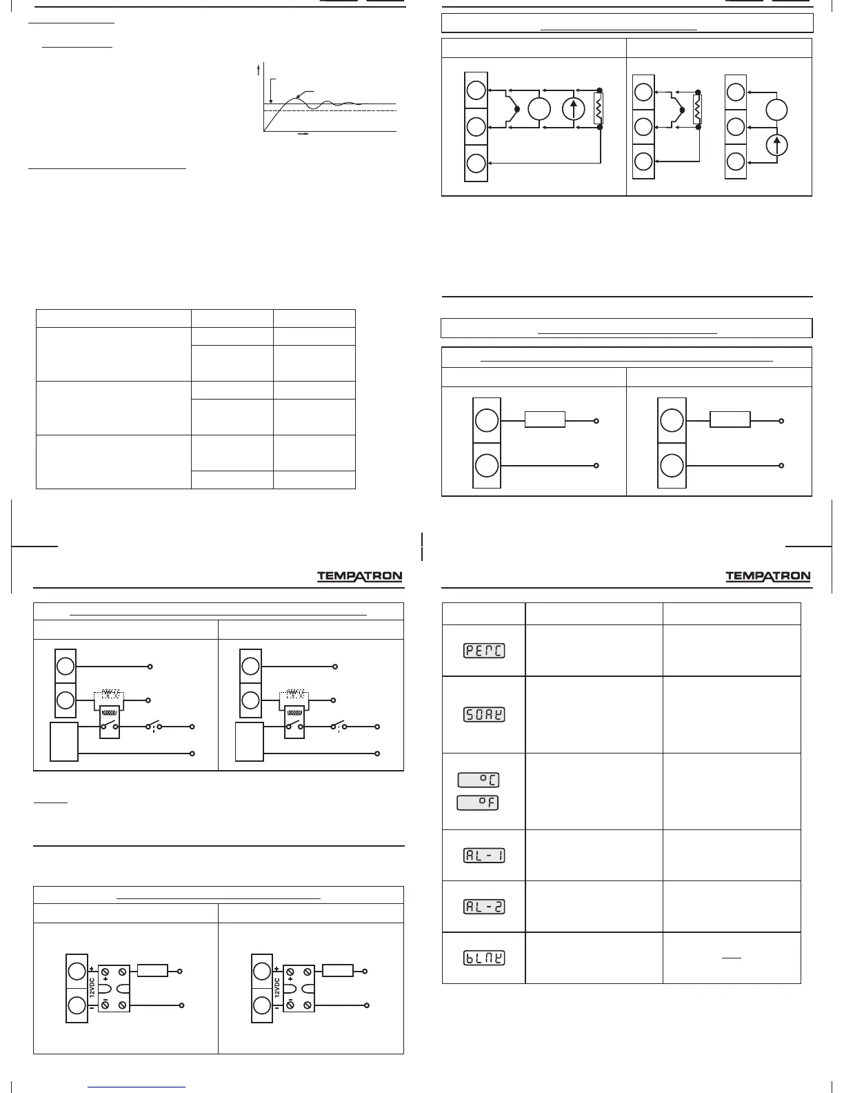
3.SENSORINPUTWIRING
TC - Thermocouple (J, K, T, R, S, C, E, B, N, L, U, W, Platinel II).
V - Voltage Input (0 to 10 V DC).
mA- Current Input (0 to 20mA DC)
RTD - PT100.
NOTE : 1) Refer input type selection in level 0 of programming menu.
2) For PID500 refer input jumper selection as in point no. 12 on page 6.
3) For 2 wire RTD short terminals 8 & 9 (for PID500) and terminals 3 & 4
(for PID110 & PID330) .
4.CONTROL OUTPUTWIRING
4
5
LOAD
230VAC
SUPPLY
NO
COM
10
Installation
RTD2
7
8
9
TC
+
-
V
+
-
+
-
mAV
RTD3
RTD1
PID500 PID110&330
PID500 PID110&330
11
12
LOAD
230VAC
SUPPLY
NO
COM
Fig1.Output1-Relaytodriveload(resistiveloadlessthan1A).
5
6
7
V
+
-
mA
V
RTD2
2
3
4
TC
+
-
RTD3
RTD1
+
-
N
L
N
L
32
DISPLAY CONDITIONDISPLAY DESCRIPTION
Outputpercentage
Elapsedsoaktime
Temperatureunit
Alarmacknowledge1
Alarmacknowledge2
Blank
Programming
This parameter is read only
and cannot be altered.
Note: This parameter is
prompted only if Ramp is ON /
Hold. This parameter is read
only and cannot be altered.
Note: This parameter is not
prompted for 0-10 V / 4-20mA.
This parameter is read only
and cannot be altered.
Note: This parameter is
prompted only if Alarm1 is ON
and Latch is ON.
Note: This parameter is
prompted only if Alarm2 is ON
and Latch is ON.
/
PID500 PID110&330
4
5
NO
Snubber(Optional)
(PartNo:APRC-01)
230VAC
SUPPLY
COM
L
LOAD
Contactor
N
Fig3.Output1-PulsedvoltagetodriveSSR.
NOTE: Use snubber as shown above to increase life of internal relay of
temperature controller.
11
Installation
4
5
LOAD
230VAC
SUPPLY
SSR
11
12
NO
Snubber(Optional)
(PartNo:APRC-01)
230VAC
SUPPLY
COM
L
LOAD
Contactor
N
Fig2.Output1-Relay/SSRtodrivecontactor(Forsinglephase).
PID500 PID110&330
11
12
LOAD
230VAC
SUPPLY
SSR
 Loading...