INSTALLATION INSTRUCTIONS Gas Furnace: (F/G)9MAE
440 01 4300 02 11
Specifications subject to change without notice.
Condensate Trap − Downflow
Orientation
When the furnace is installed in the downflow position, the
condensate trap will be initially located at the upper left corner
of the collector box, as received from the factory. See the top
image in Figure 8. When the furnace is installed in the
downflow orientation, the condensate trap must be relocated
for proper condensate drainage. See bottom image in Figure 8.
To Relocate the Condensate Trap:
Orient the furnace in the downflow position.
Figure 8 shows the condensate trap and tubing before and
after relocation. Refer to Figure 8 to begin the trap conversion.
Refer to Condensate Drain section for information how to install
the condensate drain.
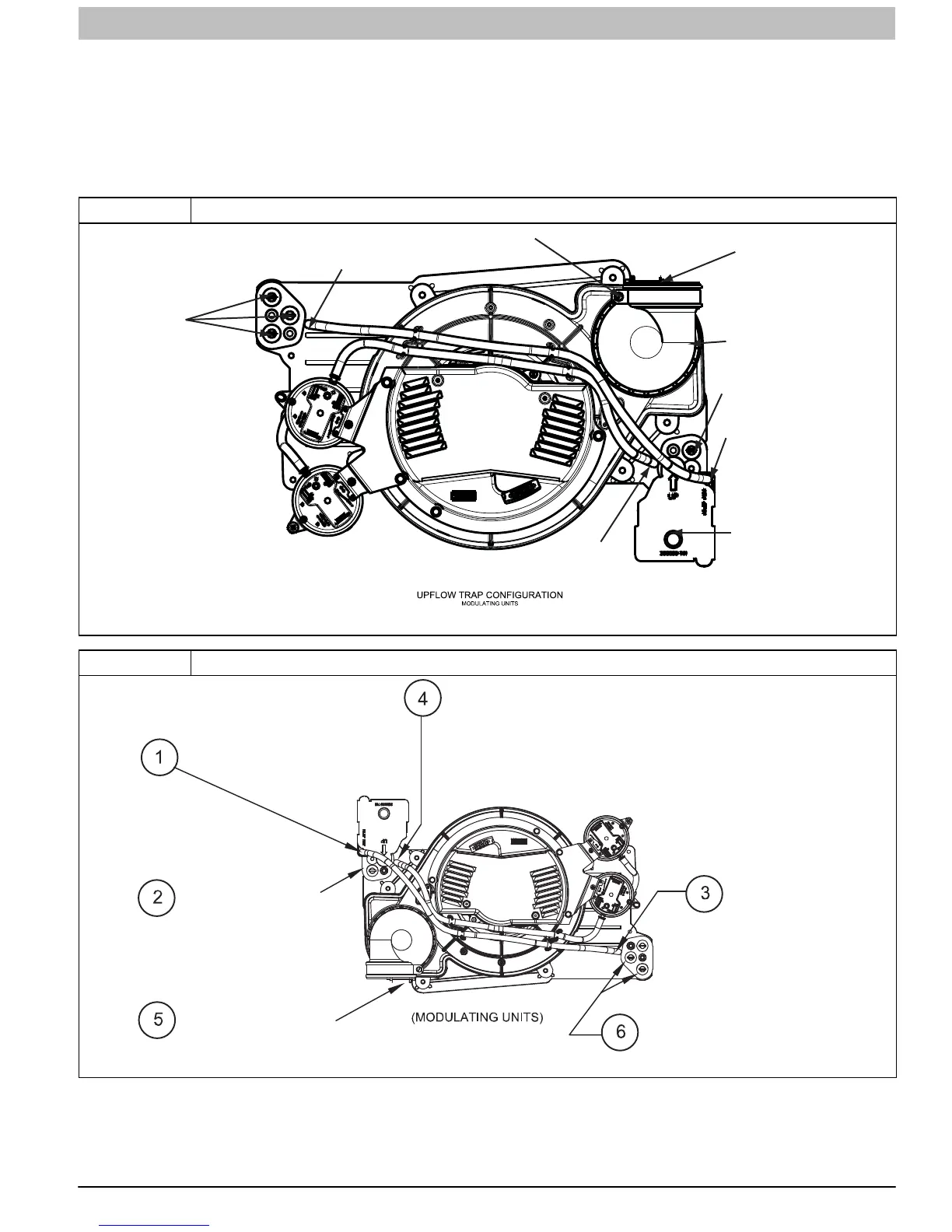
Figure 7 Upflow Trap Configuration
Condensate Trap
Relief Port
Collector Box
Plugs
Pressure Switch
Port
Condensate Trap
Outlet
Condensate Trap
Relief Port
Collector Box
Plug
Vent Elbow
Vent Elbow Clamp
Vent Pipe Clamp
A11306
Representative drawing only, some models may vary in appearance.
Figure 8 Unconverted Factory Configuration as viewed in the Downflow Orientation
Representative drawing only, some models may vary in appearance.
Remove relief tube from relief
port on condensate trap.
Remove pressure switch tube from
pressure switch port.
Remove trap from
collector box.
Loosen clamp on inlet
to vent elbow.
Remove middle and bottom plugs.
DO NOT DISCARD.
Remove tube from
relief port.
A11585A