INSTALLATION INSTRUCTIONS Gas Furnace: (F/G)9MAE
440 01 4300 02 17
Specifications subject to change without notice.
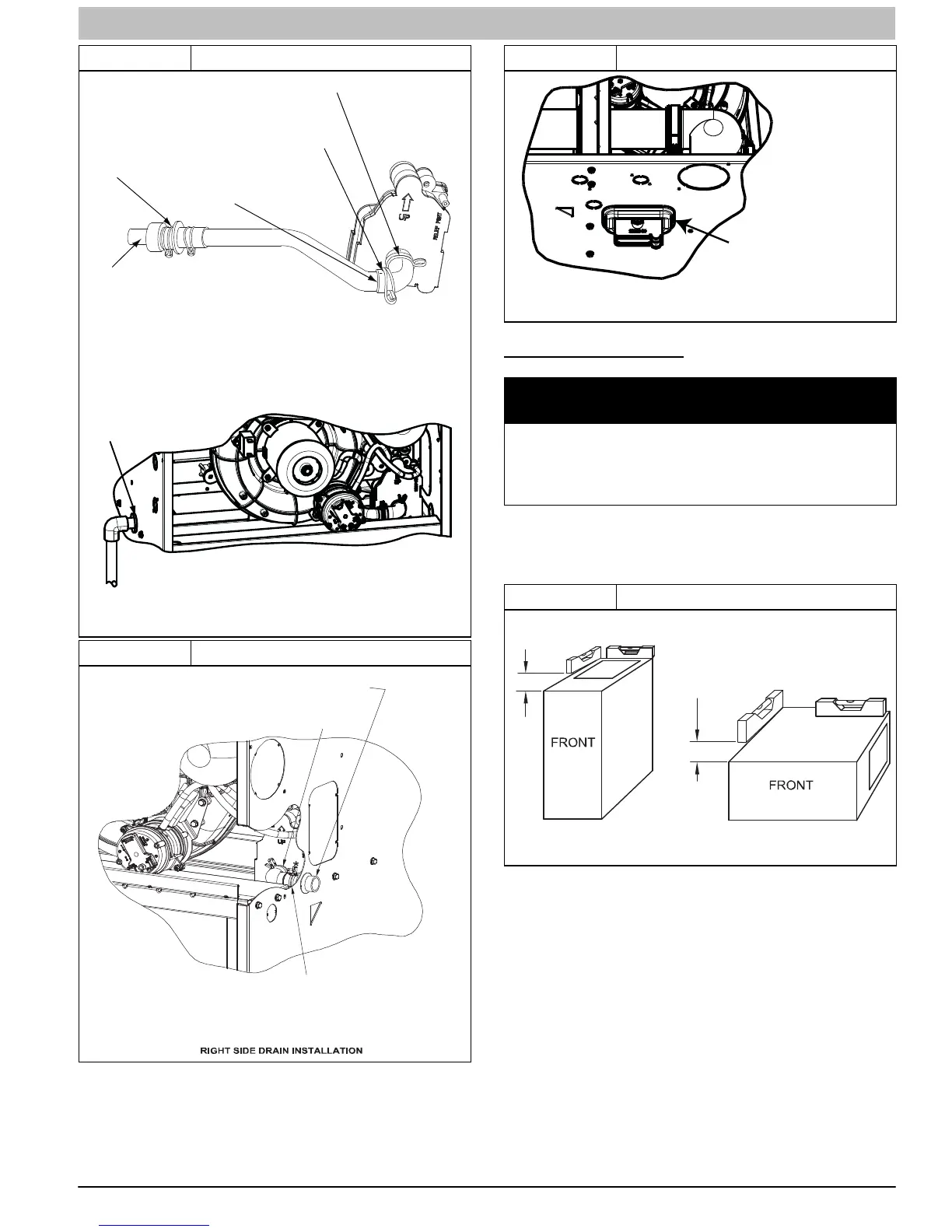
Figure 14 Drain Trap Connection and Routing
s
TRAP, DRAIN ELBOW WITH DISCHARGE PIPE
Attach elbow to condensate trap
Cut formed end off
condensate drain
elbow
Connect short end
of “Z” pipe to modified
drain elbow
Factory supplied 1/2−in. CPVC to
3/4−in. PVC adapter
LEFT SIDE DRAIN ROUTED BEHIND INDUCER
Formed end of grommet
Open spring clamp. Insert
1/2−in. to 3/4−in. CPVC to
PVC adapter or 1/2−in.
CPVC pipe
Modified drain elbow connect to
condensate trap and “Z” pipe
Formed end of
grommet
NOTE: Remove Inducer Housing for easier access, if desired.
L12F015
Figure 15 Formed Rubber Drain Grommet
L12F022
INSTALL CLAMPS ON DRAIN ELBOW
ATTACH DRAIN ELBOW TO CONDENSATE
DRAIN TRAP
PULL DRAIN STUB
THROUGH CASING
OPEN SPRING CLAMP
INSERT FACTORY−SUPPLIED 1/2−IN. CPVC
TO 3/4−IN. PVC ADAPTER OR 1/2−IN. CPVC PIPE
*CLAMP MAY BE LOCATED ON OUTSIDE OF DRAIN ELBOW
Figure 16 Horizontal Drain Trap Grommet
Remove knockout.
Install grommet before
relocating condensate
trap.
A11348
INSTALLATION
NOTICE
This furnace is certified to leak 2% or less of nominal air con-
ditioning CFM delivered when pressurized to 1-inch water
column (250 Pa) with all present air inlets (including bottom
closure in upflow and horizontal applications), air outlets, and
plumbing and electrical ports sealed.
UPFLOW INSTALLATION
NOTE: The furnace must be pitched as shown in Figure 17 for
proper condensate drainage.
Figure 17 Furnace Pitch Requirements
LEVEL 0-IN. (0 MM) TO
1/2-IN. (13 MM) MAX
UPFLOW OR
DOWNFLOW
HORIZONTAL
MIN 1/4-IN. (6 MM) TO
1/2-IN. (13 MM) MAX
A11237
Supply Air Connections
For a furnace not equipped with a cooling coil, the outlet duct
shall be provided with a removable access panel. This opening
shall be accessible when the furnace is installed and shall be of
such a size that the heat exchanger can be viewed for possible
openings using light assistance or a probe can be inserted for
sampling the air stream. The cover attachment shall prevent
leaks.
Connect supply−air duct to flanges on furnace supply−air
outlet. Bend flange upward to 90 with wide duct pliers. (See
Figure 21) The supply−air duct must be connected to ONLY
the furnace supply−outlet−air duct flanges or air conditioning
coil casing (when used). DO NOT cut main furnace casing side
to attach supply air duct, humidifier, or other accessories. All