INSTALLATION INSTRUCTIONS Gas Furnace: (F/G)9MAE
36 440 01 4300 02
Specifications subject to change without notice.
Table 13 Approved Combustion-Air and Vent Pipe, Fitting and Cement Materials (U.S.A. Installation)
ASTM
SPECIFICATION
(MARKED ON
MATERIAL)
MATERIAL PIPE FITTINGS
SOLVENT CEMENT AND
PRIMERS
DESCRIPTION
D1527
ABS Pipe − − Schedule−40
D1785
PVC Pipe − − Schedule−40
D2235
For ABS − − Solvent Cement For ABS
D2241
PVC Pipe − − SDR−21 & SDR−26
D2466
PVC − Fittings − Schedule−40
D2468
ABS − Fittings − Schedule−40
D2564
For PVC − − Solvent Cement For PVC
D2661
ABS Pipe Fittings − DWV at Schedule−40 IPS sizes
D2665
PVC Pipe Fittings − DWV
F438
CPVC − Fittings − Schedule−40
F441
CPVC Pipe − − Schedule−40
F442
CPVC Pipe − − SDR
F493
For CPVC − − Solvent Cement For CPVC
F628
ABS Pipe − −
Cellular Core DWV at Schedule−40 IPS
sizes
F656
For PVC − − Primer For PVC
F891
PVC Pipe − − Cellular Core Schedule−40 & DWV
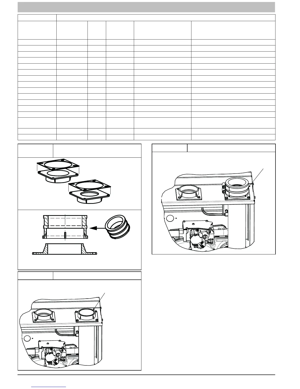
Figure 40
Vent Coupling and Adapter with
Gaskets
Attach gaskets to vent pipe and combustion air adapters
A13074
Vent Coupling and Adapter
Figure 41 Vent Pipe Flush with Adaptor
VENT PIPE ADAPTER WITH GASKET INSTALLED ON FURNACE.
VENT PIPE IS CUT FLUSH WITH TOP OF ADAPTER. PRIME AND
CEMENT VENT PIPE TO ADAPTER. ALLOW TO DRY BEFORE IN-
STALLING VENT COUPLING.
A13076A
Figure 42 Vent Pipe Flush Showing Coupling
ALIGN NOTCHES IN VENT PIPE COUPLING OVER STAND−
OFF ON ADAPTER. TORQUE LOWER CL AMP 15 LB−IN. WHEN
REMAINING VENT PIPE IS INSTALLED, TORQUE UPPER
CL AMP TO 15 LB−IN.
A13076B
Locating the Vent Termination
General
NOTE: Termination Requirements for the Provinces of
Alberta and Saskatchewan are located at the end of this
section.
Combustion−air inlet pipe (Direct Bent/2−Pipe system only) and
vent pipe must terminate outside structure, either through
sidewall or roof.
For vent termination clearance, references to National codes
are shown in Figure 58 for Direct Vent/2−Pipe system and
Figure 59 for Ventilated Combustion Air system. For exterior
termination arrangements, refer to Figure 58 for Direct
Vent/2−Pipe system and Figure 59 for Ventilated Combustion
Air system. Contact Local code authorities for other
requirements to and/or exemptions from the National codes
shown in the figures.
Roof termination is often preferred since it is less susceptible to
damage or contamination, is usually located away from
adjacent structures, is less prone to icing conditions, and often
has less visible vent vapors. Sidewall terminations may require
sealing or shielding of building surfaces with a corrosive