INSTALLATION INSTRUCTIONS Gas Furnace: (F/G)9MAE
22 440 01 4300 02
Specifications subject to change without notice.
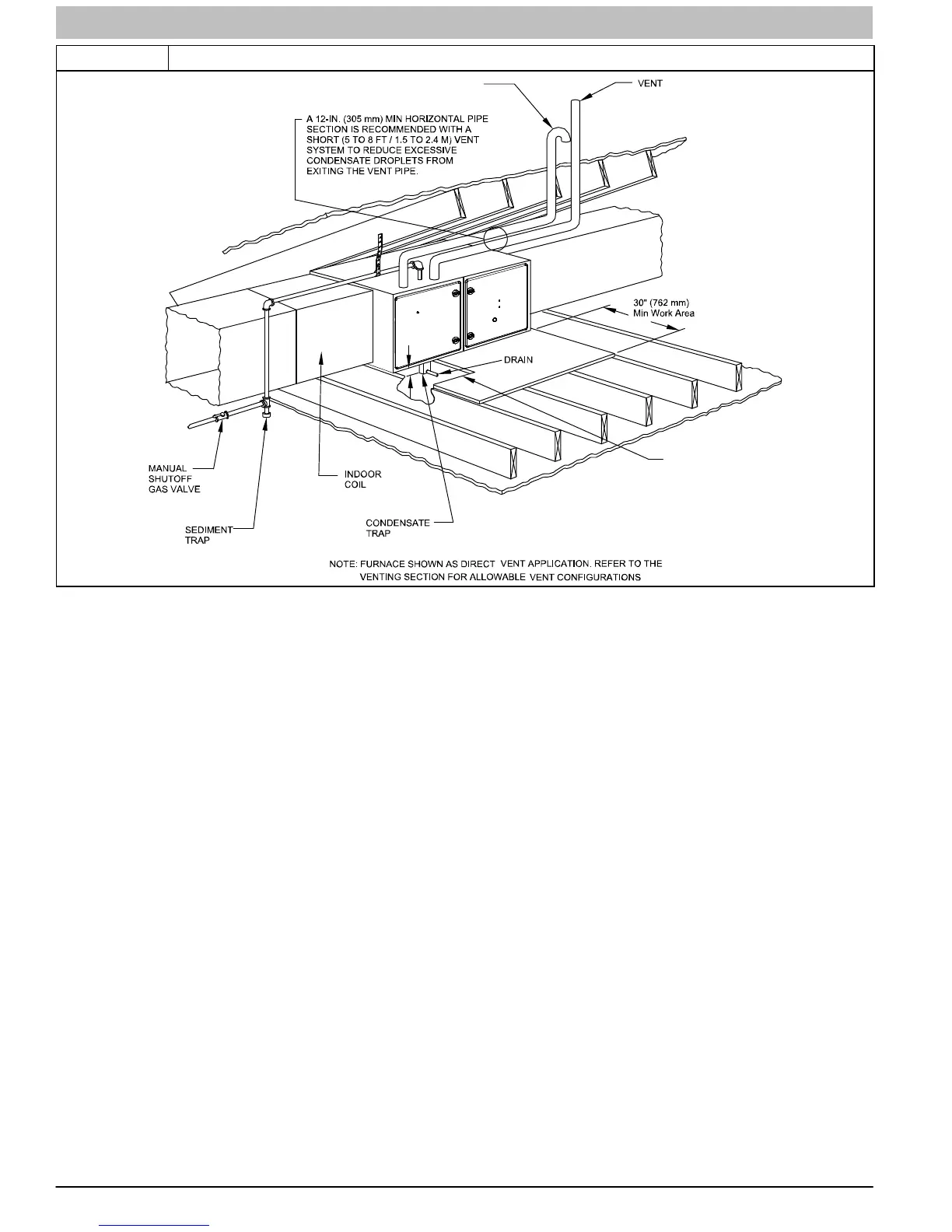
Figure 25 Working Platform for Attic Installation
2−in.
(51 mm)
A11154
ROLLOUT PROTECTION RE-
QUIRED Install 1.2” x 22” (305 x 559
mm) sheet metal in front of burner
compartment area.
COMBUSTION − AIR PIPE
(SEE VENTING SECTION)
NOTE: Local codes may require a drain pan and condensate trap when a condensing furnace is installed over a finished
ceiling
Roll−Out Protection
Provide a minimum 12−in. x 22−in. (305 x 559 mm) piece of
sheet metal for flame roll−out protection in front of burner area
for furnaces closer than 12−in. (305 mm) above the
combustible deck or suspended furnaces closer than 12−in.
(305mm) to joists. The sheet metal MUST extend underneath
the furnace casing by 1−in. (25mm) with the door removed.
The bottom closure panel may be used for flame roll−out
protection when bottom of furnace is used for return air
connection. See Figure 25 for proper orientation of roll−out
shield.
Supply Air Connections
For a furnace not equipped with a cooling coil, the outlet duct
shall be provided with a removable access panel. This opening
shall be accessible when the furnace is installed and shall be of
such a size that the heat exchanger can be viewed for possible
openings using light assistance or a probe can be inserted for
sampling the air stream. The cover attachment shall prevent
leaks.
Connect supply−air duct to flanges on furnace supply−air
outlet. Bend flange upward to 90 with wide duct pliers. (See
Figure 21) The supply−air duct must be connected to ONLY
the furnace supply−outlet−air duct flanges or air conditioning
coil casing (when used). DO NOT cut main furnace casing side
to attach supply air duct, humidifier, or other accessories. All
supply−side accessories MUST be connected to duct external
to furnace main casing.
Return Air Connections
The return−air duct may be connected to bottom of the furnace.
The side of casing that faces downward may also be used for
return air connection. A combination of the bottom and
downward facing side may also be used. The upward facing
side of the casing cannot be used as a return air connection.
(See Figure 28)
Bottom Return Air Inlet
These furnaces are shipped with bottom closure panel installed
in bottom return−air opening. Remove this panel when bottom
return air is used. This panel may be used for rollout protection
or discarded. To remove bottom closure panel, perform the
following:
1. Tilt or raise furnace and remove four (4) screws holding
bottom plate. (See Figure 18)
2. Remove bottom plate.
3. Remove bottom closure panel.
4. Reinstall bottom plate and screws.
Side Return Air Inlet
These furnaces are shipped with bottom closure panel installed
in bottom return−air opening. This panel MUST be in place
when side return air inlet(s) are used without a bottom return air
inlet.
Not all horizontal furnaces are approved for side return air
connections (See Figure 28)
 Loading...


