INSTALLATION INSTRUCTIONS Gas Furnace: (F/G)9MAE
46 440 01 4300 02
Specifications subject to change without notice.
19. Use appropriate methods to seal openings where
combustion air pipe and vent pipe pass through roof or
sidewall.
!
WARNING
CARBON MONOXIDE POISONING HAZARD
Failure to follow this warning could result in personal
injury or death.
DO NOT use cement to join polypropylene venting
systems. Follow the polypropylene venting system
manufacturer’s instructions for installing polypropylene
venting systems.
Optional Installation of the vent pipe
NOTE: DO NOT USE THIS TECHNIQUE FOR
POLYPROPYLENE VENTING SYSTEMS.
This option provides a disconnect point for the vent pipe. The
vent pipe must be cemented to the plastic vent pipe adapter to
maintain a sealed vestibule. See Figure 41 and Figure 42
1. Insert a length of vent pipe through the casing into the
outlet of the vent elbow.
2. Slide the plastic vent pipe adapter over the length of the
vent pipe down to the furnace casing. Mark the pipe
where it is flush with the outlet of the adapter.
3. Remove the pipe from the furnace and the adapter and
cut off any excess pipe.
4. Clean and prime the end of the pipe that is flush with the
vent adapter with a primer that is appropriate for the type
of pipe being used.
5. Re−insert the pipe through the casing into the vent
elbow.
6. Tighten the clamp around the outlet of the vent elbow.
Torque the clamp to 15 lb−in.
7. Apply cement to the end of the pipe and to the inside of
the plastic vent adapter.
8. Slide the adapter over the vent pipe and align the screw
holes in the adapter with the dimples in the furnace
casing.
9. Pilot drill 1/8−in. screw holes for the adapter in the casing
and secure the adapter to the furnace with sheet metal
screws.
10. Loosen the clamps on the rubber vent coupling.
11. Slide the end of the coupling with notches in it over the
standoffs in the vent pipe adapter.
12. Tighten the clamp of the coupling over the vent pipe
adapter. Torque the lower clamp around the vent pipe
adapter to 15 lb−in.
13. Pilot drill a 1/8−in. hole in the combustion air pipe
adapter.
14. Complete the vent and combustion air pipe as shown in
“Install the Vent and Combustion Air Pipe”
NOTICE
For Polypropylene Venting Systems
When using polypropylene venting systems, all venting ma-
terials used, including the vent terminations, must be from the
same manufacturer.
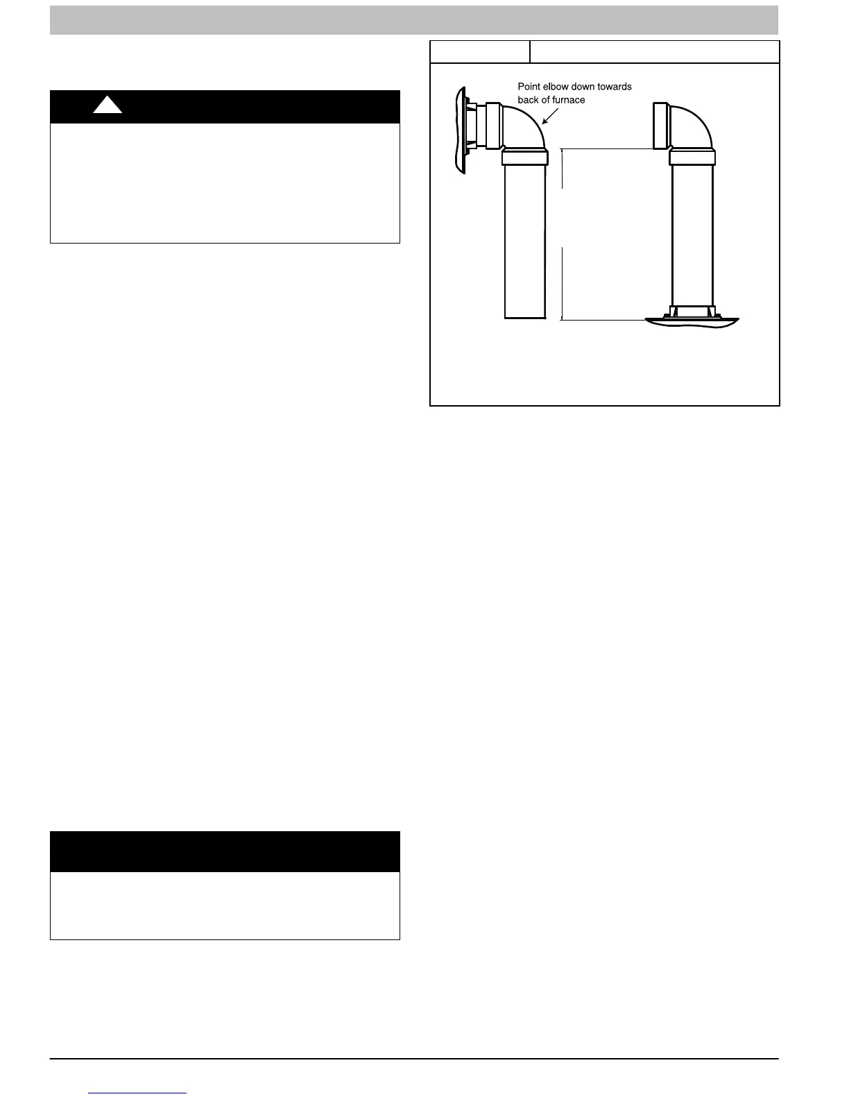
Figure 55 Combustion Air Pipe
A13406
12" (256mm) minimum
to
60”(1524 mm) or
1 additional elbow maximum
CASING SIDE OR TOP ATTACHMENT
COMBUSTION AIR PIPE
(NON-DIRECT VENT FOR ALL MODELS EXCEPT MODULATING UNLESS
INSTALLED IN ATTIC OR CRAWL SPACE)
Installing the Vent Termination
Roof Terminations
A roof termination of any type will require a 4-in. (102 mm)
flashing for a 2−in. (50 mm ND) concentric vent or a 5−in. (127
mm) diameter flashing for a 3-in. (80 mm ND) concentric vent
kit. For 2-pipe or single pipe vent systems, a flashing for each
pipe of the required diameter will be necessary.
It is recommended that the flashing be installed by a roofer or
competent professional prior to installing the concentric vent.
The terminations can be installed on a flat or pitched roof.
Concentric Vent
Single or multiple concentric vent must be installed as shown in
Figure 46. Maintain the required separation distance between
vents or pairs of vents as shown in Figure 46 and all
clearance shown in Figure 58.
NOTE: Follow the instructions of the vent terminal
manufacturer. These instructions are provided as a reference
only.
Cut one 4−in. (102 mm) diameter hole for 2−in. (50 mm ND) kit,
or one 5−in. (127 mm) diameter hole for 3−in. (80 mm ND) kit in
the desired location.
Loosely assemble concentric vent/combustion air termination
components together using instructions in kit.
Slide assembled kit with rain shield REMOVED through hole in
wall or roof flashing.
NOTE: Do not allow insulation or other materials to accumulate
inside of pipe assembly when installing it through hole.
Disassemble loose pipe fittings. Clean and cement using same
procedures as used for system piping. DO NOT CEMENT
POLYPROPYLENE FITTINGS.
Two−Pipe (Direct Vent)Terminations
Two pipe vent terminals must be installed as shown in
Figure 46 and Figure 47. Maintain the required separation
distance between vents or pairs of vents as shown in
Figure 46 and Figure 47 and all clearance shown in Figure 58
or Figure 59.

 Loading...

