INSTALLATION INSTRUCTIONS Gas Furnace: (F/G)9MAE
440 01 4300 02 43
Specifications subject to change without notice.
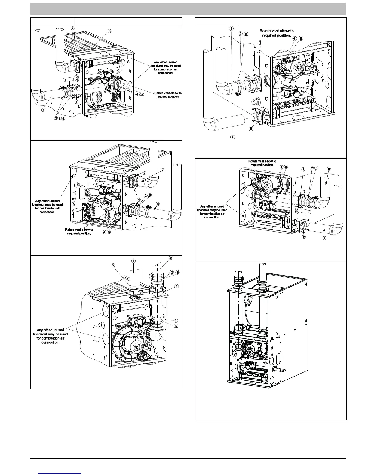
Figure 51 Upflow Configurations
A11309
Representative drawing only, some models may vary in appearance.
UPFLOW LEFT − VENT CONFIGURATION
A11308
Representative drawing only, some models may vary in appearance.
UPFLOW RIGHT − VENT CONFIGURATION
A11310
Representative drawing only, some models may vary in appearance.
UPFLOW VERTICAL − VENT CONFIGURATION
* See NOTES following figures.
Figure 52 Downflow Configurations
A11311
Representative drawing only, some models may vary in appearance.
DOWNFLOW LEFT − VENT CONFIGURATION
A11312
Representative drawing only, some models may vary in appearance.
DOWNFLOW RIGHT − VENT CONFIGURATION
L11F063
Representative drawing only, some models may vary in appearance.
Requires Accessory Internal Vent Kit
See Specification Sheets for current kit number
DOWNFLOW VERTICAL − VENT CONFIGURATION
* See NOTES following figures.