TEMPTRONE
CORPORATION
Rev.
B:
04/15/98
TP04
100A Operator's
Manual
3.
USER
INTERFACE
r
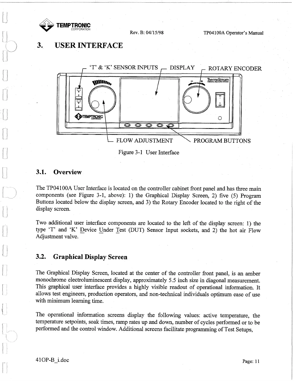
'T'
&
'K'
SENSOR INPUTS
,-
DISPLAY
,
ROTARY
ENCODER
FLOW ADJUSTMENT S
Figure 3-1 User Interface
3.1.
Overview
The TP04100A User Interface is located on the controller cabinet front panel and has three main
components (see Figure
3-1,
above): 1) the Graphical Display Screen, 2) five
(5)
Program
Buttons located below the display screen, and
3)
the Rotary Encoder located to the right of the
display screen.
Two additional user interface components are located to the left of the display screen: 1) the
type
'T'
and
'K'
-
Device Under Test (DUT) Sensor Input sockets, and 2) the hot air Flow
-
-
Adjustment valve.
3.2.
Graphical Display Screen
The Graphical Display Screen, located at the center of the controller front panel, is
an
amber
monochrome electroluminescent display, approximately
5.5
inch size in diagonal measurement.
This graphical user interface provides a highly visible readout of operational information. It
allows test engineers, production operators, and non-technical individuals optimum ease of use
with minimum learning time.
The operational information screens display the following values: active temperature, the
temperature setpoints, soak times, ramp rates up and down, number of cycles performed or to be
performed and the control window. Additional screens facilitate programming of Test Setups,
Page: 11
Artisan Technology Group - Quality Instrumentation ... Guaranteed | (888) 88-SOURCE | www.artisantg.com
 Loading...