10
NEED MORE HELP?
Support: http://support.teradek.com → Contains tips, information and all the latest rmware & software updates.
TERADEK SUPPORT STAFF: support@teradek.com or call 888−941−2111 ext2 (Mon−Fri 6am to 6pm PST)
Insert a SIM card into each SIM
card slot.
Power on Link Pro using AC power,
or install a battery if Link Pro is
equipped with a Gold or V mount
battery plate.
Connect all four nodes to Link Pro
using 4-pin to 4-pin data/power
cables.
1
3
2
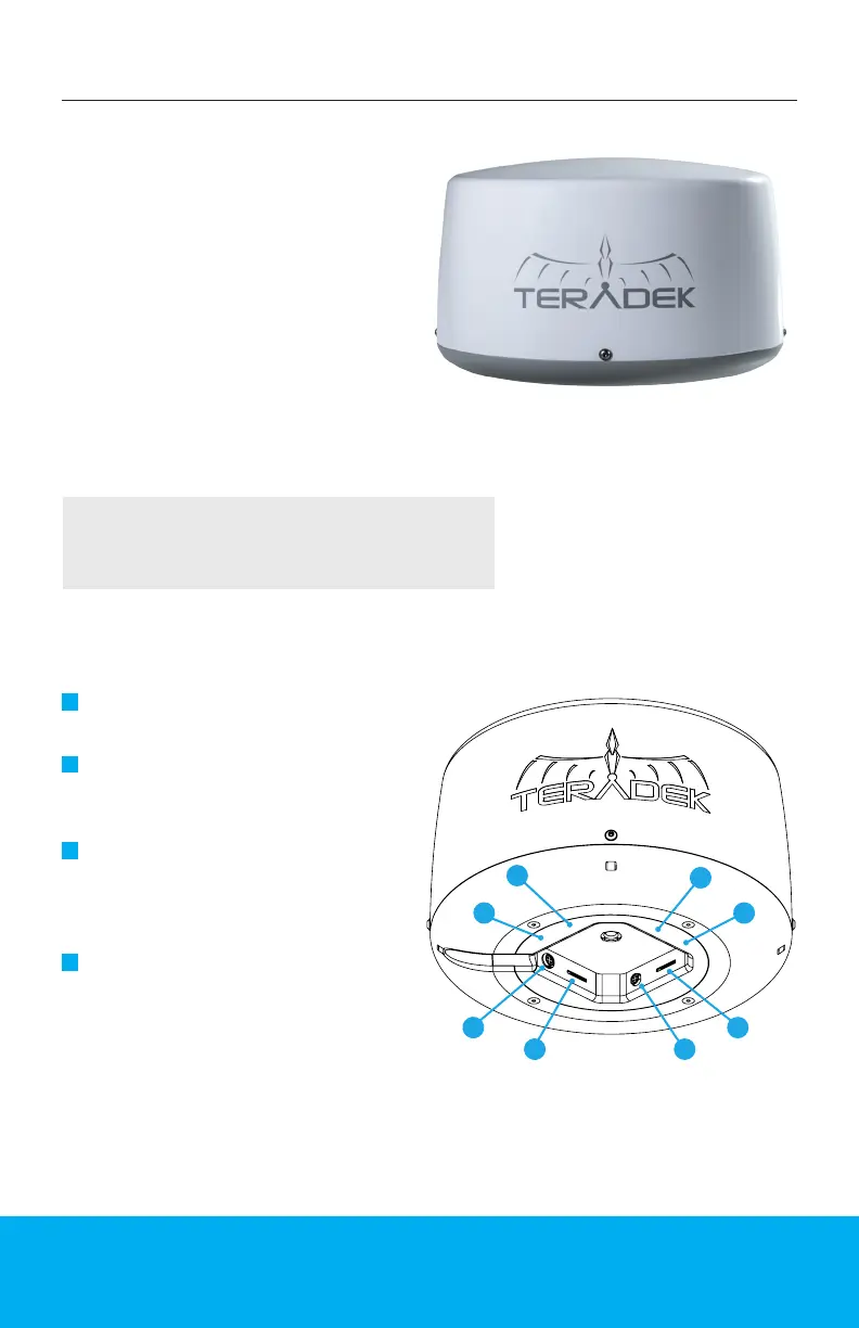
Link Pro Radome contains four
3G/4G/LTE modems and attaches
to a standalone Link Pro for
optimized antenna placement.
Link Pro Radome is designed to
endure the harshest of elements
and provide a consistent Internet
connection anywhere you
go, making it perfect for xed
installations and/or vehicular
applications.
NOTE: All four Nodes power up and connect to the cellular
network automatically when connected to a Link Pro modem.
Connect to one of Link Pro’s Wi-Fi
networks: Link-Pro-XXXXX or
Link-Pro-XXXXX 5G (XXXXX is the
last ve digits of the device’s serial
number).
4
Assembly and Power
LINK PRO RADOME
G
H
A
F
E
D
C
A: SIM card slot 1
B: 4-pin data/power input 1
C: SIM card slot 2
D: 4-pin data/power input 2
E: SIM card slot 3
F: 4-pin data/power input 3
G: SIM card slot 4
H: 4-pin data/power input 4
B