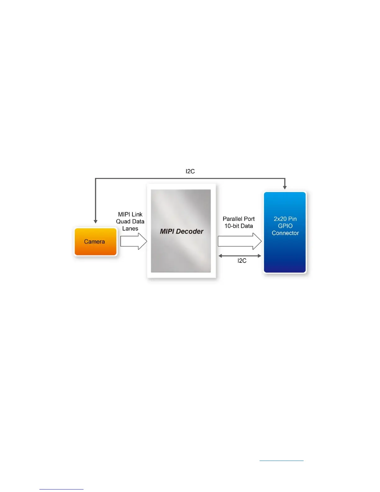
3.2 MIPI Decoder
The MIPI camera module output interface is MIPI interface, which cannot directly
connect to the Terasic FPGA board; therefore, a MIPI Decoder (TC358748XBG) is
added to convert MIPI interface to a parallel port interface (See Figure 3-3). Decoder
users can quickly obtain the image data and process it. MIPI Decoder can convert MIPI
Interface up to 24-bit data. The Camera module used on the D8M can only output 10
bit data, MIPI_PIXEL_D[9:0] the GPIO connector is the camera image output data bus,
and MIPI_PIXEL_D[13:10] is reserved for an alternative camera module with more
output bits.
Figure 3-3 System Overview with MIPI Decoder in CSI-2 RX to Parallel Port
Configuration
FPGA also can read/write MIPI Decoder through a I2C bus (MIPI_I2C_SDA /
MIPI_I2C_SCL ; I2C device address is 0x1C), which is different from the camera
module I2C bus. On the D8M board, MIPI Decoder can output clocks to the MIPI
camera and FPGA board. So in the demonstrations, most of them show how to control
IC PLL parameters as well as others. You can refer to section 3-4 clock tree for details.
 Loading...