It’s a system including sensors able to detect lifted load,
boom position, a main unit and a control panel situated
inside at the cabin.
Which components are included in an LMI?
4
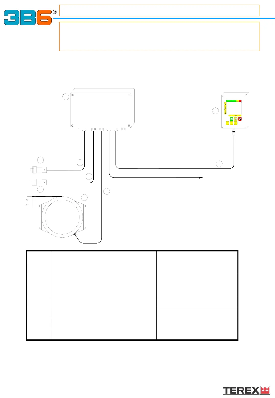
SYSTEM LAY
SYSTEM LAY
-
-
OUT MEGAMAC.106
OUT MEGAMAC.106
AND CONNECTIONS
AND CONNECTIONS
6
1
7
2
CV 4X0.5+SCH
CV 4X0.5+SCH
PG6
PG5PG4PG3
PG2
PG1
J1
B
A
LOW CHAMBER (BOTTOM SIDE)
AND EXTERNAL SUPPLY
INPUT OUTPUT SIGNALS
HIGH CHAMBER (ROD SIDE)
4
5
5
3
A2B
4
Ref. Description Code
1 Main unit U2MIC-X/XX
2 Control panel CMC1-XXX/XX
3 Cable reel AC MCP214A/3P
4 Pressure transducer Y11 4745-350
5 Cable CV 4x0.5+SCH
6 Cable CV 8x0.35+SCH
7 Cable CV ATG12/XX