Home
Terrain King
Lawn Mower
KB21
Page 49 (Bucher L.8 S Open Center Directional Control Valve, Manual Control)
Terrain King KB21 - Bucher L.8 S Open Center Directional Control Valve, Manual Control
126 pages
Manual
Save Page as PDF
To Next Page
To Next Page
To Previous Page
To Previous Page
Loading...
KB21 Service Manual Pub 09-14
49
Cylinder Control Systems
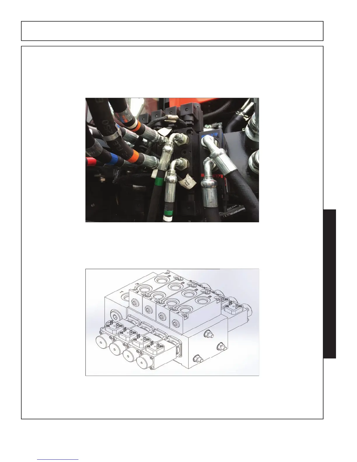
40-A. Bucher L.8S Manual/Control Cable
Bucher Series L.8S Open Center Directional Control Valve, Manual Control
L.8S, 4 Spool control valve
L.8S, 4 S
poo
l co
nt
ro
l valve.
48
50
Table of Contents
Main Page
Default Chapter
4
Table of Contents
4
Section 10 - Safety
7
General Safety Instructions and Practices
8
Operator Safety Instructions and Practices
9
Connecting & Disconnecting Implement Safety Instructions and Practices
12
Equipment Operation Safety Instructions and Practices
12
Maintenance and Service Safety Instructions and Practices
18
Transporting Safety Instructions and Practices
21
Concluding Safety Instructions and Practices
22
Decal Locations
23
Decal Descriptions
25
Federal Laws and Regulations
31
Tractor Side Definition
32
Mounting Work Site Requirements
33
Warning: Do Not Weld
34
Section 30 - Hydraulics
35
30-A Hydraulic Control Circuits
37
Boom Control Circuits
39
30-B Hydraulic Tank Repair
41
30-C Gear Pumps
43
Hydraulic Power to Motor
43
Gear Motor and Tandem Gear Pump Operation
43
Tandem Pumps
44
Motor Circuit Control Valve Operation
46
Motor Control Valve Function
47
Section 40 - Cylinder Control Systems
48
40 -A. Bucher Series L.8S Open Center Directional Control Valve, Manual Control
49
Cylinder Hydraulic Control Circuit
50
One Way Restrictors
52
Valve Sections Function
52
Hose End Fitting Torque Specification
52
Work Port Relief Operation
54
Anti-Cavitation Check/Work Port Relief Operation
55
Control Circuit Main Relief Valve Operation
56
Remote Cable Operation and Installation
57
Control Assembly - Controller End - Installation Procedure
59
Mechanical Control Valve
61
Valve Ports
62
40 -B. Bucher Series L.8S Open Center Directional Control Valve, Electrical Control
63
General Operation
65
Joystick Functions
66
Electrical Signals
67
Emergency Stop (E-Stop) Switch
69
Control Valves
70
Fixed Displacement Valve End Cap
71
Valve Section Components
72
Valve Spool Functions & Specs
74
Section 60 - Motors and Spindles
75
60-A Rotary Mowers
75
Typical Modes of Failure
77
Motor Mount Flange (Spindle Housing) Breaking or Cracking
81
60-B Spindle Assembly Repair
83
Spindle Housing
84
Spindle Housing Inspection
87
Spindle Housing Assembly
88
Section 80: Testing
93
80-A Mechanical Control Valve
94
Section 90: References
97
90-A Pump Repair
97
90-B Pump Repair - Part Location
97
90-E PVG32 Troubleshooting
97
90-C Pump Shaft Issues
111
90-D Hydraulic System Operation
113
90-F Safety References
117