KB21 Service Manual Pub 09-14
50
Cylinder Control Systems
40-A. Bucher L.8S - Manual Control/Cable
Cylinder Hydraulic Control Circuit
Hydraulic power for the cylinder control circuit is taken from the second (smaller) stage of the hydraulic
pump. Oil is supplied to the spool control valve where it is directed to the appropriate cylinder through
the cylinder hoses. All of the cylinders are double acting requiring a hose to supply pressure oil for
each direction. The system is protected from excessive pressure by an adjustable pressure relief valve
located on the inlet section of the control valve. The pressure relief valve is factory set at 2000 PSI
on the KB21 Boom. In addition, some individual cylinder circuits are protected by a nonadjustable work
port relief valve (See Specifications).
The port relief valves set specific pressures for the boom function to provide over-pressure protection.
-
Oil is returned from the valve through the motor control valve to the tank where it passes through the
The valve utilized on the KB21 mowers facilitates the control of the boom movement functions is a
4 spool, open center, sectional, manually, or electrically, operated valve. The manual operation is
performed with the use of normal directly attached valve handles or through the use of cables and
remote mechanical levers.
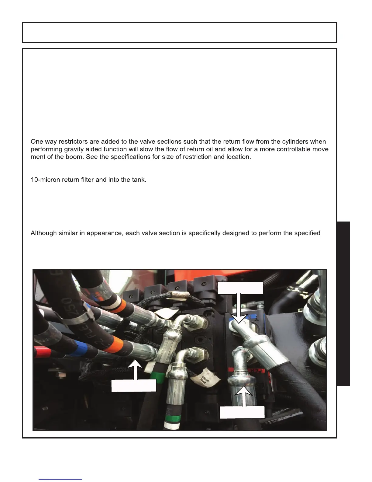
function for which it is assigned.
Some of the major components are shown below.
RETURN
PRESSURE
SPOOLS