KB21 Service Manual Pub 09-14
59
Cylinder Control Systems
40-A. Bucher L.8S Manual Control/Cable
Control Assembly - Controller End -
Installation Procedure
Each controller assembly comes fully assembled.
All required hardware etc. is included. The control
cables are not included with the control handles
and should be ordered separately.
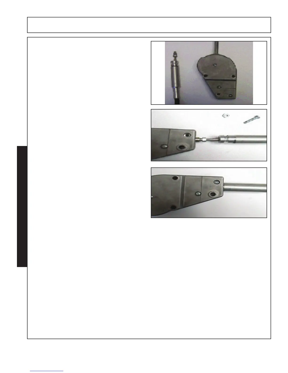
To attach the cable, manipulate the controller
handle so that the attachment nut is exposed as
shown. Remove the lower most nut and screw from
the controller housing.
Thread the cable nut into the controller attachment
nut and tighten.
Allow the controller handle to return to neutral.
Slide the cable guide tube into the control housing
and reinstall and tighten the housing screw.
Check the operation of the spool, cable and
controller. Some adjustment at the valve end may
be required too ensure that the spool returns to
neutral when the controller is in the neutral position.
The control lever assemblies utilize a small spring to make up for free play in the cable to valve
connection.
The control valve spool spring provides the centering capabilities of the controller and the valve spool.
Lack of centering at the controller is normally attributed to poor adjustment at the valve to cable
connection or binding of the cables due to poor routing.